Variable-speed scroll-type refrigeration compressor

a refrigeration compressor and variable speed technology, applied in the direction of arcuate-engagement type engines, rotary piston engines, rotary or oscillating piston engines, etc., can solve the problems of reducing the lubrication of its various parts, reducing the performance of the compressor, and reducing the lubrication of the compressor. , to achieve the effect of reducing greenhouse gas emissions, enhancing the protection of the injection pipe, and facilitating maintenan

Active Publication Date: 2010-04-22
DANFOSS COMML COMPRESSORS
View PDF6 Cites 12 Cited by
  • Summary
  • Abstract
  • Description
  • Claims
  • Application Information

AI Technical Summary

Benefits of technology

[0032]The attachment of the solenoid valve to the wall of the sealed enclosure allows easy maintenance of the solenoid valve because the latter is easily accessible from the outside of the compressor.
[0033]Moreover, this attachment of the solenoid valve to the wall of the sealed enclosure avoids the creation of openings in the sealed jacket for the passage of the supply and injection pipes, and avoids having at least some of these pipes on the outside of the sealed jacket. This enhances the protection of the injection pipe and hence of the compressor against external impacts and stresses and reduces greenhouse gas emissions.
[0034]Advantageously, the body of the solenoid valve comprises a first body portion attached to the wall of the enclosure and a second body portion attached removably to the first body portion, outside of the sealed enclosure, the second body portion containing the solenoid valve core. This structure of the solenoid valve body further facilitates the maintenance of this solenoid valve.

Problems solved by technology

Thus, when the rotor is turning slowly, the amount of oil circulating with the refrigerant gas is low, which can lower the performance of the compressor and reduces the lubrication of its various parts.
On the other hand, when the rotor is turning fast, the proportion of oil in the refrigerant gas leaving the compressor can become excessive.
The direct consequence of this excessive proportion of oil in the gas is less efficient heat exchange by the exchangers situated downstream of the compressor.
In addition, an excessive proportion of oil in the gas can also drain the oil sump.
This could lead to destruction of the compressor.
This calibration of the elasticity of the compression spring acting on the valve is complex and cannot be performed accurately.
As a result, the means employed in document U.S. Pat. No. 6,322,339 are complex and cannot be used to accurately control the injection of oil into the compression volume.
The means used in document U.S. Pat. No. 6,322,339 do not therefore keep the performance of the compressor constant.
Another disadvantage with this type of oil injection line is the fact that particles can insinuate themselves between the walls of the housing in which the valve slides, and the valve itself.
These particles can interfere with the operation of the valve and therefore with that of the oil injection line.
In addition, locating the valve inside the barrel means that the valve is difficult to maintain.
In particular, it is difficult to replace the compression spring or clean out the housing in which the valve slides.
However, the arrangement of the supply and injection pipes, which are at least partly outside of the sealed jacket, can lead to rupturing of the pipes as a result of unforeseen impacts or stresses during maintenance of the compressor.
Creating such openings can allow leaks of refrigerant fluids into the atmosphere and therefore increase greenhouse gas emissions.

Method used


Image

  • Variable-speed scroll-type refrigeration compressor
  • Variable-speed scroll-type refrigeration compressor
  • Variable-speed scroll-type refrigeration compressor

Examples


Embodiment Construction

[0058]In the following description, the same parts are given the same reference signs in the different embodiments.

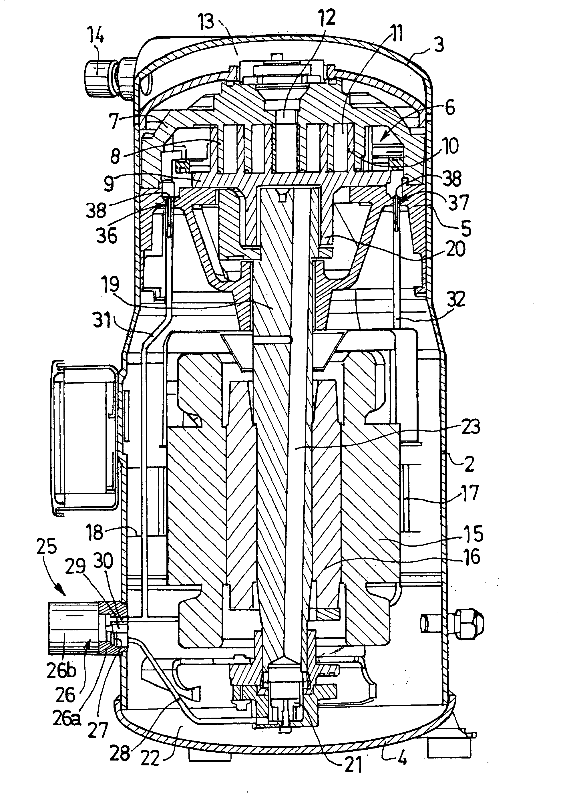
[0059]FIG. 1 shows a variable-speed scroll-type sealed refrigeration compressor occupying a vertical position. However, the compressor according to the invention could occupy an inclined position, or a horizontal position, without significant modification to its structure.

[0060]The compressor shown in FIG. 1 comprises a sealed enclosure defined by a barrel 2 whose top and bottom ends are closed by a cap 3 and a base 4 respectively. Weld seams may for example be used to assemble this enclosure.

[0061]The intermediate part of the compressor is occupied by a body 5 that defines two volumes, a suction volume situated beneath the body 5, and a compression volume located above the latter. The barrel 2 comprises a refrigerant gas inlet leading into the suction volume to bring the gas to the compressor.

[0062]The body 5 serves as a mounting for the refrigerant gas compression sta...


PUM


Abstract

The compressor includes a sealed housing defining a suction volume and a compression volume respectively provided on either side of a body contained in the housing, an oil injection circuit supplied with oil from an oil contained in a casing and adapted for injecting oil into the compression volume, the oil injection circuit comprising an electrovalve including a body attached to the wall of the sealed housing and a core movable under the action of a magnetic fluid between a closing position for injecting oil into the compression volume and an opening position preventing or limiting the injection of oil into the compression volume. The compressor includes a control means for moving the core of the electrovalve between the opening and closing positions based on the compressor speed and/or on the cooling gas discharge temperature.

Description

BACKGROUND OF THE INVENTION[0001]The present invention relates to a variable-speed scroll-type refrigeration compressor.DESCRIPTION OF THE PRIOR ART[0002]Document FR 2 885 966 describes a scroll compressor, also known as a scroll pump, comprising a sealed enclosure defined by a barrel defining a suction volume and a compression volume, one on either side of a body contained within the enclosure. The barrel defining the sealed enclosure comprises a refrigerant gas inlet.[0003]An electric motor is located inside the sealed enclosure, with a stator on the outside, fixed relative to the barrel, and a rotor in a central position connected to a crankshaft-like drive shaft which has a first end driving an oil pump supplying oil from a sump in the bottom of the enclosure to a lubrication way in the center of the shaft. The lubrication way comprises lubrication ports for each guide bearing of the drive shaft.[0004]The compression volume contains a compression stage comprising a fixed volute ...

Claims


Application Information

Patent Timeline
Patent Type & Authority Applications(United States)
IPC IPC(8): F01C1/02F04C29/02
CPCF04C29/021F04C18/0215
Inventor BODART, JEAN-PAULROSSON, YVES
Owner DANFOSS COMML COMPRESSORS
Why Eureka
Try Eureka