Assembled battery, manufacturing method of the same, and vehicle provided with assembled battery

a manufacturing method and battery technology, applied in the direction of cell components, sustainable manufacturing/processing, wound/folded electrode electrodes, etc., can solve the problems of increasing the cost of the container made of such a thin material, affecting the performance of the battery, and limiting the mounting space of the assembled battery

Active Publication Date: 2010-04-22
TOYOTA JIDOSHA KK
View PDF9 Cites 31 Cited by
  • Summary
  • Abstract
  • Description
  • Claims
  • Application Information

AI Technical Summary

Benefits of technology

[0006]This invention thus provides an assembled battery which evens out the shape of unit cells that form the assembled battery, particularly the thickness (size) in a predetermined arranging direction of the unit cells while they are fastened with a load applied in the arranging direction, and thus minimize, in advance, variation in distance between, and relative positions of, the unit cells, or more specifically, positive and negative electrode terminals for connecting the unit cells together in series. The invention also provides a method for manufacturing that assembled battery and a vehicle provided with that assembled battery.

Problems solved by technology

However, it is given that assembled batteries which are mounted in a vehicle such as an automobile are subject to limitations with respect to mounting space and will be used in an environment where vibrations occur.
However, a container made of such a thin material tends to deform under an external load.
Thus, an increase in cost and a decrease in work efficiency related to the work of connecting the positive and negative electrode terminals may result.
Moreover, deformation of the unit cell containers that occurs when the unit cells are fastened together may result in the containers and electrode bodies of the unit cells no longer being sealed (air-tight) (i.e., the seal (air-tightness) may be lost).

Method used


Image

  • Assembled battery, manufacturing method of the same, and vehicle provided with assembled battery
  • Assembled battery, manufacturing method of the same, and vehicle provided with assembled battery
  • Assembled battery, manufacturing method of the same, and vehicle provided with assembled battery

Examples


Embodiment Construction

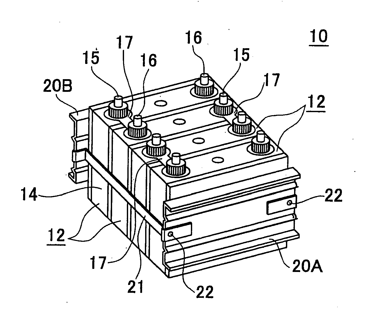
[0026]In the following description and the accompanying drawings, the present invention will be described in more detail in terms of example embodiments. An assembled battery 10 according to the invention is able to be used as an electric motor power source that is mounted in a vehicle such as an automobile, in particular. Therefore, the invention also provides a vehicle (i.e., particularly a vehicle provided with an electric motor, such as a hybrid vehicle, an electric vehicle, or a fuel cell vehicle) 1 provided with this assembled battery 10, as shown in frame format in FIG. 6. In this specification, the term “unit cell” refers to an individual power storing element that can be connected to another individual power storing element (i.e., unit cell) in series to form an assembled battery.

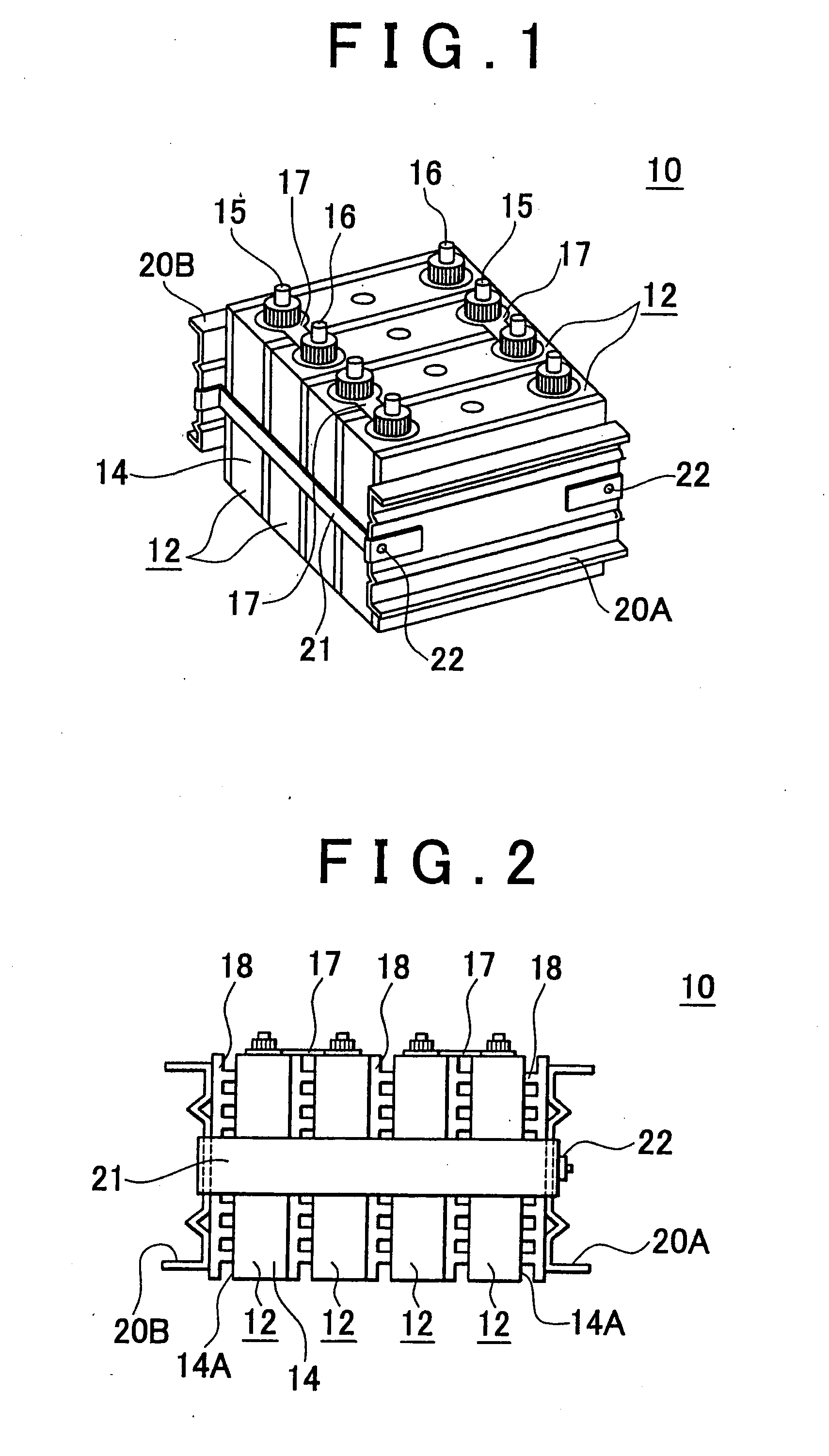
[0027]The assembled battery of the invention may be formed by connecting a plurality of individual rechargeable secondary batteries, which serve as the unit cells, together in series. However, the ...


PUM

PropertyMeasurementUnit
thicknessaaaaaaaaaa
thicknessaaaaaaaaaa
surface pressureaaaaaaaaaa

Abstract

In an assembled battery (10), a plurality of rechargeable unit cells (12), each of which is provided with an electrode body (30) that has a positive electrode (32) and a negative electrode (34), a container (14) that houses the electrode body (30) and an electrolyte, and a positive electrode terminal (15) and a negative electrode terminal (16) which are arranged on an outside of the container (14), the rechargeable unit cells being connected in series. The plurality of unit cells (12) are arranged in a predetermined direction and fastened together while a predetermined load is applied in the arranging direction. Insulating filler (25) is inserted into a gap between the electrode body (30) and an inside wall surface of the container (14) of at least one of the unit cells (12), and a thickness in the arranging direction of each of the unit cells (12) in the fastened state is constant.

Description

BACKGROUND OF THE INVENTION[0001]1. Field of the Invention[0002]The invention relates to an assembled battery in which a plurality of rechargeable unit cells are connected in series, a manufacturing method of this assembled battery, and a vehicle provided with this assembled battery.[0003]2. Description of the Related Art[0004]An assembled battery, which is formed by connecting a plurality of unit cells which may be lithium ion batteries (cells) (in this specification, the terms “battery” and “cell” have the same meaning and may be used interchangeably) which are light and are capable of obtaining high energy density, nickel-metal hydride batteries, other secondary batteries, or power storing elements such as capacitors, together in series, is a power source from which high output can be obtained. For this reason, assembled batteries are gaining importance as in-vehicle power sources or power sources for personal computers and portable terminals. Japanese Patent Application Publicat...

Claims


Application Information

Patent Timeline
Patent Type & Authority Applications(United States)
IPC IPC(8): H01M6/42H01M6/00H01M10/04H01M50/209H01M50/264H01M50/291H01M50/293H01M50/51
CPCH01M2/0245Y10T29/49108H01M2/206H01M10/0413H01M10/0431H01M10/0468H01M10/0481H01M10/0525H01M10/0585H01M10/0587H01M10/5004H01M10/5016H01M10/5032H01M10/5046H01M10/5059Y02T10/7011H01M2/1077H01M10/625H01M10/647H01M10/6551H01M10/6557H01M10/613Y02E60/10Y02P70/50H01M50/258H01M50/293H01M50/209H01M50/264H01M50/51H01M50/291H01M10/38H01M50/50B60L50/50
Inventor KURODA, AKIRATAKEDA, SACHIOSAKAI, YASUHIKO
Owner TOYOTA JIDOSHA KK
Why Eureka
Try Eureka