
Seamless multilayer composite pipe

a composite pipe and seamless technology, applied in the field of manufacturing a seamless multi-layer composite pipe, can solve the problems of high production cost, reduced output rate, and need for skilled operators, and achieve the effect of reducing cos

Active Publication Date: 2010-04-29
HALCOR METAL WORKS
View PDF2 Cites 15 Cited by
  • Summary
  • Abstract
  • Description
  • Claims
  • Application Information

AI Technical Summary

Benefits of technology

[0006]It is therefore an object of the present invention to provide an improved method of manufacturing a seamless multilayer composite pipe, an advanced apparatus for manufacturing a seamless multilayer composite pipe, and an improved seamless multilayer composite pipe.
[0010]According to this first aspect, the method for manufacturing a multilayer composite pipe does not require complicated apparatus for manufacturing, involves simpler processing steps and is capable of increased output rates and reduced manufacturing costs.
[0015]In the second aspect of the present invention, an apparatus for manufacturing a seamless multilayer composite pipe comprises a unit for providing a seamless metal pipe with at least one continuous layer covering its inner surface, and a unit for reducing the diameter of the seamless metal pipe by cold working.

Problems solved by technology

These lead in turn to excessive use of metal, complicated machinery, the need for skilled operators and reduced output rates, resulting in higher production costs.
Welded multilayer pipes exhibit reduced strength to hydrostatic sustained pressure due to their lower strength resulting from the welded metal layer.
In addition, the quality of the welded metal tube is controlled with difficulty as far as the resultant fusion strength is concerned, so these tubes exhibit an increased probability to develop welding failures (hidden defects), hence a decreased local strength.

Method used


Image

  • Seamless multilayer composite pipe
  • Seamless multilayer composite pipe
  • Seamless multilayer composite pipe

Examples


Embodiment Construction

Method of Manufacturing a Seamless Multilayer Composite Pipe

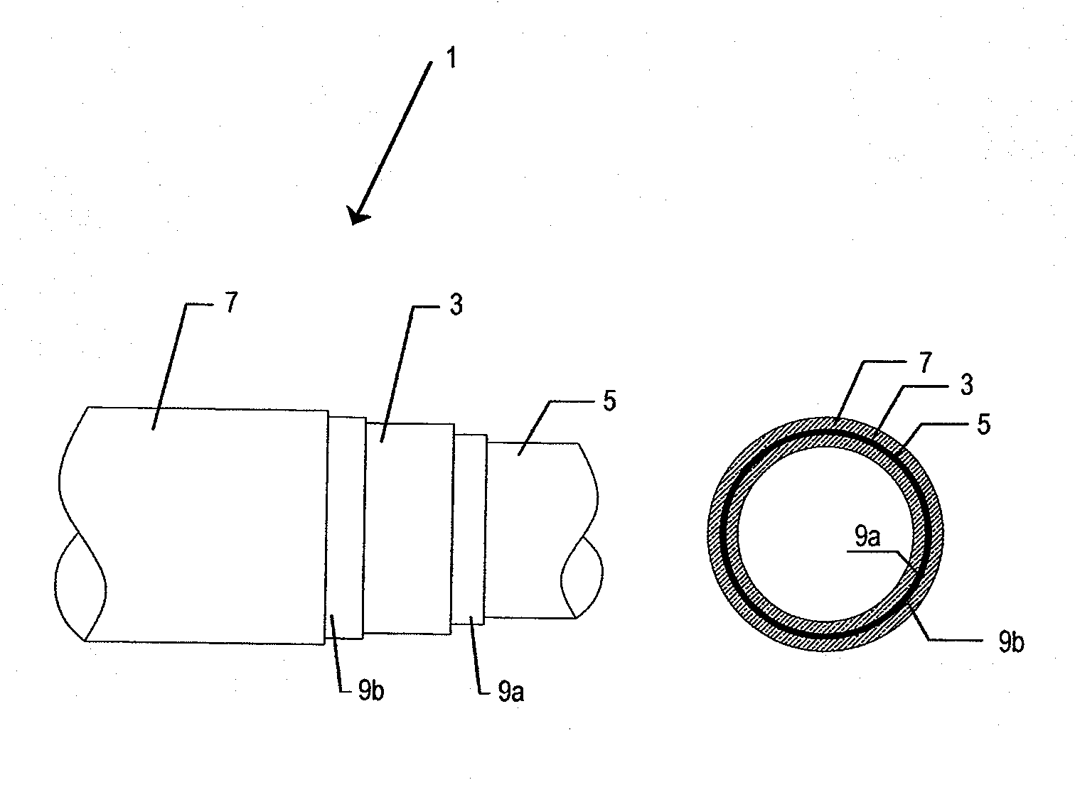
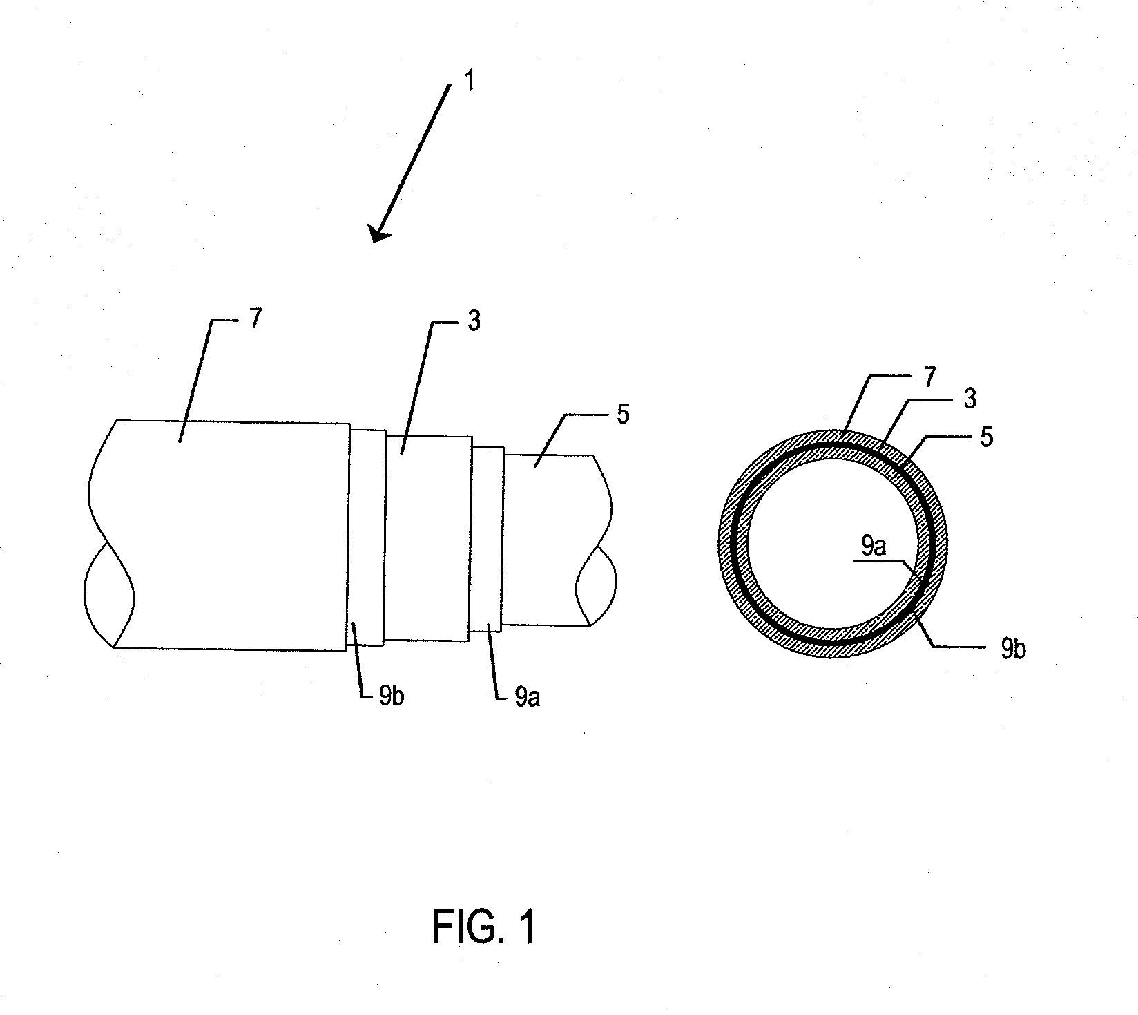
[0032]The method of manufacturing a seamless multilayer composite pipe 1 comprises the steps of

[0033]a) providing a seamless metal pipe 3 with at least one continuous layer 5 covering its inner surface, and

[0034]b) passing the seamless metal pipe 3 through a unit 109, 209 in order to reduce the diameter of the seamless metal pipe 3 by cold working.

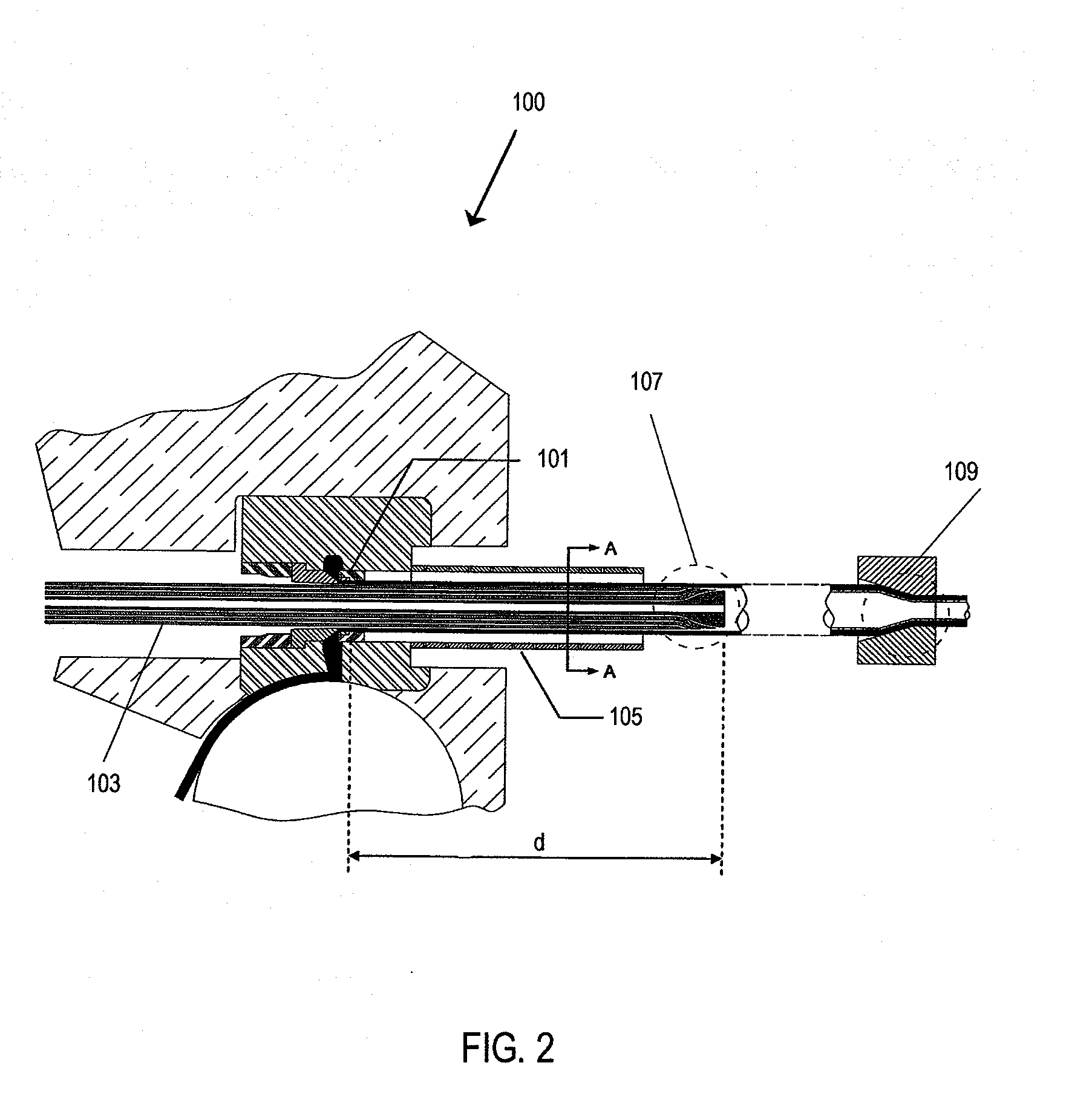
[0035]In this method of manufacturing a seamless multilayer composite pipe 1, as a first alternative, in step a) the seamless metal pipe 3 is provided with at least one continuous layer 5 covering its inner surface by the further steps of

[0036]a1) adjusting a distance d between a hot-extrusion die 101 and a co-extrusion head 107 in the direction of extrusion of the seamless metal pipe 3;

[0037]a2) feeding metal material to the hot-extrusion die 101;

[0038]a3) feeding adhesive material through a channel 111 and feeding material for the continuous layer 5 through a channel 113 to the ...


PUM

PropertyMeasurementUnit
Diameteraaaaaaaaaa

Abstract

The present invention relates to a method of manufacturing a seamless multilayer composite pipe, an apparatus for manufacturing a seamless multilayer composite pipe, and a seamless multilayer composite pipe. The method of manufacturing a seamless multilayer composite pipe comprises the steps of a) providing a seamless metal pipe with at least one continuous layer covering its inner surface, and b) passing the seamless metal pipe through a unit in order to reduce the diameter of the seamless metal pipe by cold working. An apparatus for manufacturing a seamless multilayer composite pipe comprises a unit for providing a seamless metal pipe with at least one continuous layer covering its inner surface, and a unit for reducing the diameter of the seamless metal pipe by cold working.; A seamless multilayer composite pipe comprises a seamless metal pipe with at least one continuous layer covering its inner surface, wherein the continuous layer covering the inner surface of the a seamless metal pipe is mechanically compressed.

Description

FIELD OF THE INVENTION[0001]The present invention relates to a method of manufacturing a seamless multilayer composite pipe, an apparatus for manufacturing a seamless multilayer composite pipe, and a seamless multilayer composite pipe.RELATED PRIOR ART[0002]Multilayer composite pipes built up from two concentric plastic layers with an intermediate layer of aluminium, mostly an aluminium foil, are conventionally made in subsequent steps by extruding a plastic pipe, covering it with a layer of adhesive and then wrapping around it a thin sheet or foil of aluminium. Finally an additional layer of adhesive and an external layer of plastic are applied, probably by extrusion to complete the compound structure.[0003]To ensure strength and stability of the metal layer, the aluminium sheet or foil must be applied in transversely or obliquely overlapping fashion or be seam-welded using a TiG or a laser welding arrangement. These lead in turn to excessive use of metal, complicated machinery, th...

Claims


Application Information

Patent Timeline
IPC IPC(8): B21C23/24F16L9/147B29C48/09B29C48/152
CPCB21C23/005B29C47/022B29C47/0023B21C23/30B29C48/09B29C48/152
Inventor BIRIS, JOHNHINOPOULOS, GEORGEKAIMENOPOULOS, APOSTOLOS
Owner HALCOR METAL WORKS
Learn More