Dynamic Centering Fixture with Hydraulic Load Delivery Compensation

a technology of hydraulic load and centering fixture, which is applied in the direction of forging/pressing/hammering apparatus, forging/hammering/pressing machines, manufacturing tools, etc., can solve the problems of difficult manual positioning of workpieces, difficult to achieve accurate workpiece placement, and more difficult to precisely position workpieces

Inactive Publication Date: 2010-04-29
KADANT INC
View PDF0 Cites 18 Cited by
  • Summary
  • Abstract
  • Description
  • Claims
  • Application Information

AI Technical Summary

Benefits of technology

[0007]It is seen from the foregoing that there is a need for an apparatus and method for accurately and reliably locating a workpiece

Problems solved by technology

The more difficult a workpiece is to handle because of any physical aspect of the workpiece, the more difficult precise placement of the workpiece becomes.
Accurate workpiece placement under such conditions is not easily achieved but is desirable because it often results in reduced processing time and labor required to properly finish the end product.
The manual positioning method described above, when used in forging processes, requires close human proximity to the heavy and hot, up to 2500° F., workpieces, creating the risk of personal injury.
This increases the difficulty in precise manual positioning of the workpiece.
Further still, the manual met

Method used


Image

  • Dynamic Centering Fixture with Hydraulic Load Delivery Compensation
  • Dynamic Centering Fixture with Hydraulic Load Delivery Compensation

Examples


Embodiment Construction

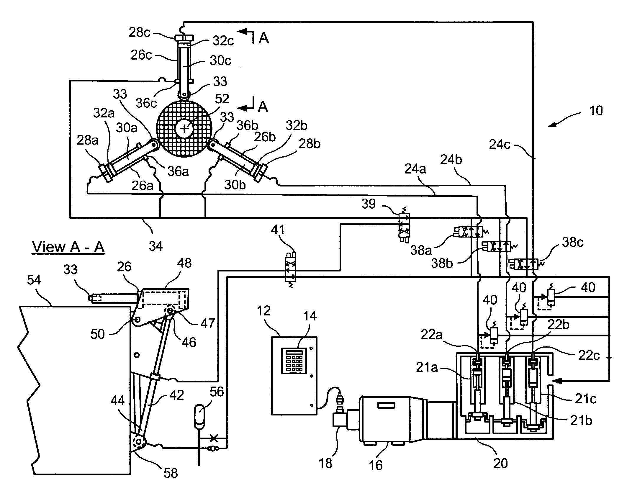
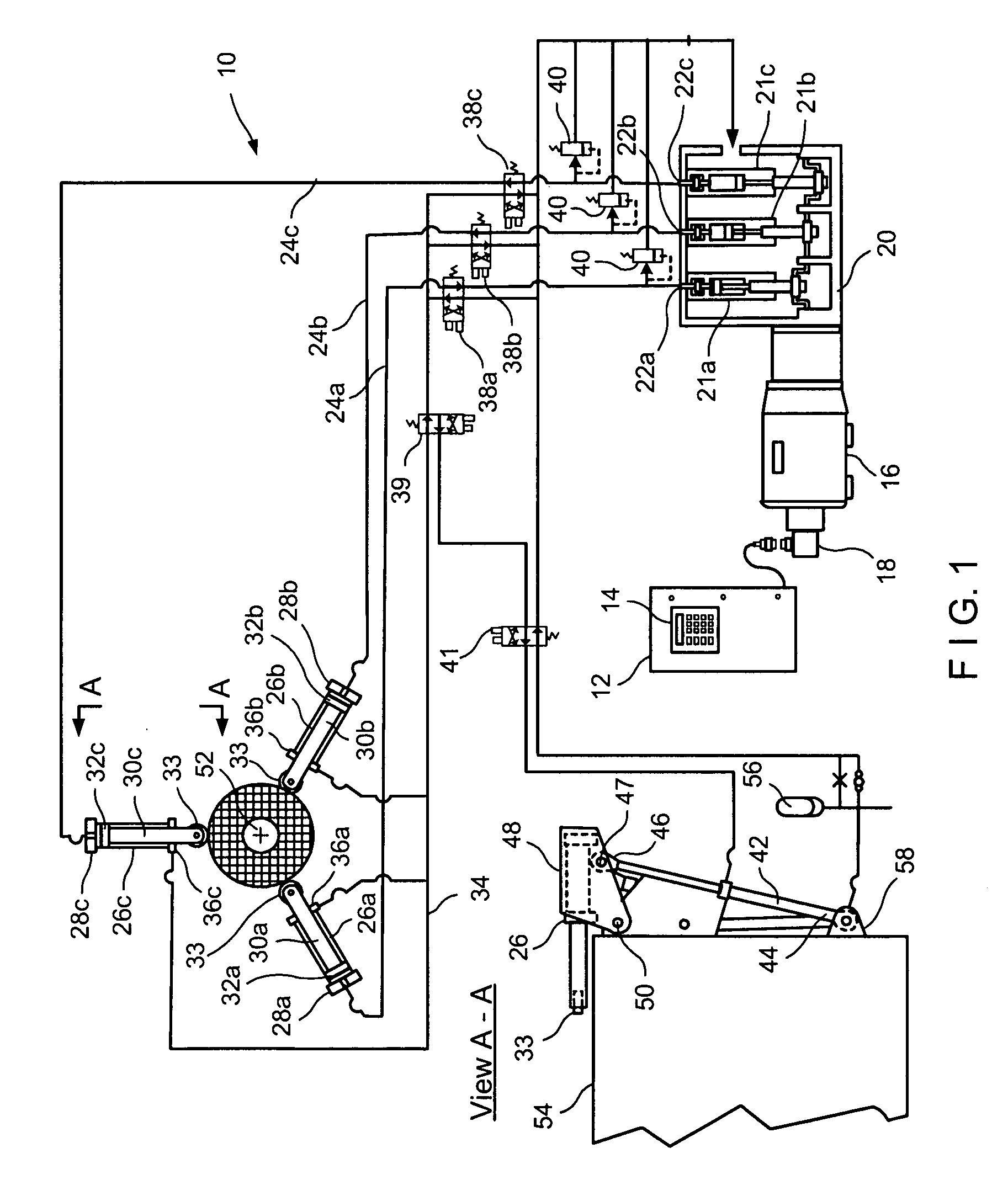
[0017]The invention will now be described more fully hereinafter with reference to the accompanying drawings, in which exemplary embodiments of the invention are shown. This invention may, however, be embodied in many different forms and should not be construed as limited to the illustrated embodiments set forth herein. Rather, these illustrated embodiments are provided so that this disclosure will be thorough and complete, and will convey the scope of the invention to those skilled in the art.

[0018]In the disclosure, the claimed centering device is described with regard to use in a forging process. This is for convenience only. As one of ordinary skill in the art will appreciate, the disclosed centering apparatus has utility in many industrial applications, not limited to forging. The disclosed apparatus is useful in industrial applications in which the workpiece cannot be easily positioned manually, or manual positioning does not yield satisfactory results, or in which the working...


PUM

PropertyMeasurementUnit
Speedaaaaaaaaaa

Abstract

A dynamic centering apparatus, suitable for centering a workpiece on a work surface, comprising a plurality of hydraulic actuators coupled to individual cells of a hydraulic pump.

Description

FIELD OF THE INVENTION[0001]The present invention relates, in general, to workpiece centering for industrial processing. More particularly, the present invention provides an apparatus and a method for positioning a workpiece. Even more particularly, the present invention provides an apparatus and a method for centering a cylindrical metal ingot for central piercing in a punch press.BACKGROUND OF THE INVENTION[0002]In many industrial applications it is necessary to handle workpieces that are unwieldy because of their weight, size, material, temperature, or other physical characteristics, for placement or fixturing the workpiece. The more difficult a workpiece is to handle because of any physical aspect of the workpiece, the more difficult precise placement of the workpiece becomes. In situations in which the workpiece cannot be handled by humans because of the physical characteristics of the workpiece, or because of the environment in which the work must be performed, or both, materi...

Claims


Application Information

Patent Timeline
IPC IPC(8): B21D28/04B23Q3/10B23Q7/06B21D28/36B23Q7/00
CPCB21J13/10B23Q3/183B21K1/761
Inventor CARSTENSEN, PETER T.
Owner KADANT INC
Why Eureka
Try Eureka