Power steering apparatus of watercraft with propeller

Inactive Publication Date: 2010-04-29
SHOWA CORP
View PDF1 Cites 3 Cited by
  • Summary
  • Abstract
  • Description
  • Claims
  • Application Information

AI Technical Summary

Benefits of technology

[0008]An object of the present invention is to simply suppress a gyro effect caused by a rotational reacti

Problems solved by technology

In the watercraft mentioned above, if the watercraft steering person loses hold of the steering handle for fishing or the like while the hull is traveling, the propelling unit is steered in the rightward direction mentioned above, and the hull can not maintain the previous traveling direction before release of the steering hand

Method used


Image

  • Power steering apparatus of watercraft with propeller
  • Power steering apparatus of watercraft with propeller
  • Power steering apparatus of watercraft with propeller

Examples


embodiment 1 (figs.1 to 4c)

Embodiment 1 (FIGS. 1 to 4C)

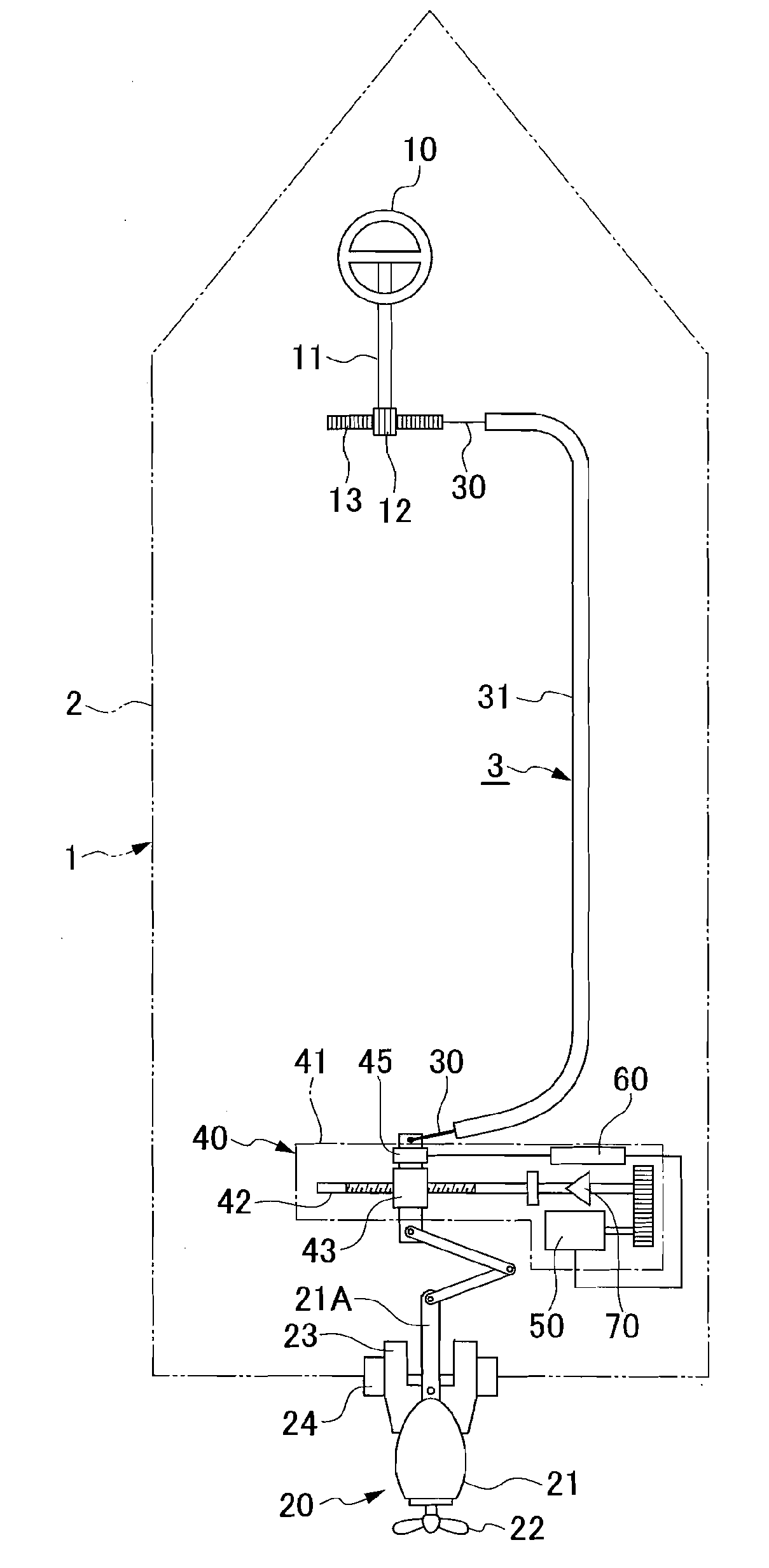
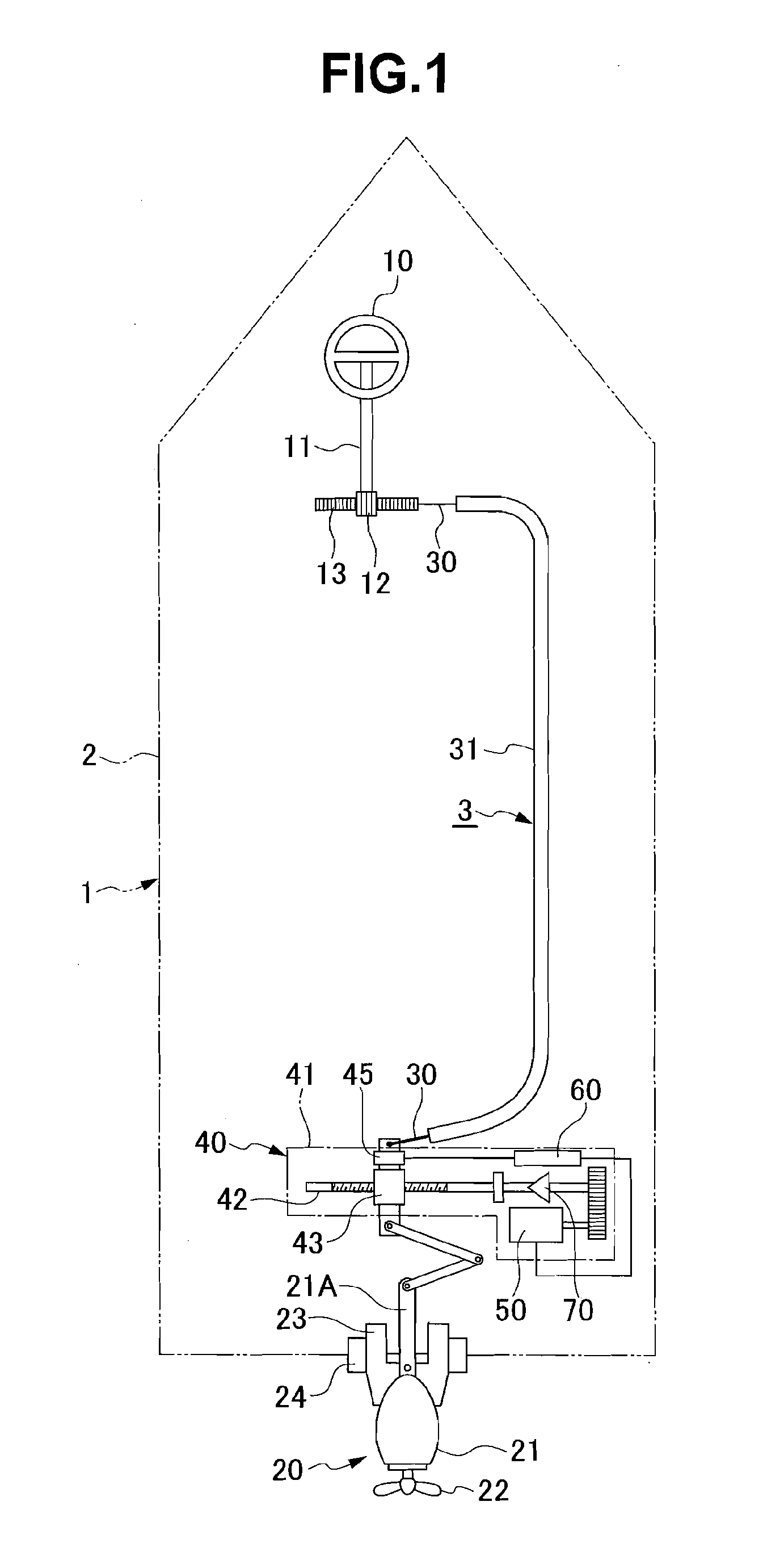
[0027]A watercraft 1 shown in FIG. 1 has a steering handle 10 provided in a bow end of a hull 2, an outboard motor 20 serving as a propeller provided in a stern end of the hull 2, and a steering cable 30 serving as a steering force transmission path transmitting a steering force applied to the steering handle 10 to the outboard motor 20. The steering cable 30 is extended within an outer tube 31 installed in the stern end from the bow end in an inner portion of the hull 2.

[0028]The steering handle 10 is installed in a control seat in the bow end of the hull 2. A pinion 12 fixed to a handle shaft 11 of the steering handle 10 is engaged with a rack 13, and the rack 13 is coupled to one end of the steering cable 30. The steering handle 10 is rotated leftward or rightward on the basis of an application of a steering force (a steering torque), whereby the steering cable 30 is pushed and pulled via an engagement between the pinion 12 and the rack 13.

[0029]The ou...

embodiment 2 (figs.5 and 6)

Embodiment 2 (FIGS. 5 and 6)

[0047]A difference between a power steering apparatus 3 of a watercraft 1 in accordance with an embodiment 2 shown in FIGS. 5 and 6 and the embodiment 1 is that the torque sensor 45 and the control unit 60 arranged within the gear case 41 of the steering assist apparatus 40 are moved.

[0048]The torque sensor 45 is provided on the handle shaft 11 of the steering handle 10. In other words, the handle shaft 11 is structured such that an input shaft 11A to which the steering handle 10 is directly coupled, is coaxially coupled to an output shaft 11B to which the pinion 12 is directly coupled, via a torsion bar (not shown), and the torque sensor 45 is interposed between the input shaft 11A and the output shaft 11B. Accordingly, the torque sensor 45 is structured such as to detect the steering direction and the steering torque applied by the watercraft steering person to the steering handle 10.

[0049]The control unit 60 is arranged on one side of the steering hand...

embodiment 3 (fig.7)

Embodiment 3 (FIG. 7)

[0051]A difference between a power steering apparatus 3 of a watercraft 1 in accordance with an embodiment 3 shown in FIG. 7 and the embodiment 1 is that a steering assist apparatus 90 taking the place of the steering assist apparatus 40 is arranged around the steering handle 10 in the bow end in the inner portion of the hull 2.

[0052]The steering assist apparatus 90 is arranged within a gear case 91 fixed to the hull 2. The steering assist apparatus 90 is structured such that the handle shaft 11 of the steering handle 10 is separated into two sections including the input shaft 11A to which the steering handle 10 is directly couple, and the output shaft 11B to which the pinion 12 is directly coupled, the input shaft 11A and the output shaft 11B are coaxially coupled via a torsion bar (not shown), and a torque sensor 92 is interposed between the input shaft 11A and the output shaft 11B. The torque sensor 92 detects the steering direction and the steering torque ap...


PUM


Abstract

In a power steering apparatus of a watercraft with propeller applying an assist torque of an assist motor driven in correspondence to a steering direction and a steering force of a steering handle to a steering force transmission path to the propeller, an output side of the assist motor is provided with an inverse input interrupting apparatus transmitting an assist torque of the assist motor to the steering force transmission path, and interrupting an inverse input torque applied to the steering force transmission path from a side of the propeller caused by a rotational reaction force of a screw provided in the propeller with respect to the assist.

Description

BACKGROUND OF THE INVENTION[0001]1. Field of the Invention[0002]The present invention relates to a power steering apparatus of a watercraft with a propeller such as an outboard motor, an inboard outboard motor and the like.[0003]2. Description of the Related Art[0004]In a power steering apparatus of a watercraft with outboard motor, there is a power steering apparatus structured to apply an assist torque of a motor-driven assist motor (or a motor-driven assist pump of a hydraulic power steering apparatus) driven in correspondence to a steering direction and a steering force of a steering handle to a steering force transmission path to the outboard motor, as described in Japanese Patent Application Laid-Open No. 2004-231108 (patent document 1). It is structured such as to assist a manual steering force applied by a watercraft steering person to the steering handle on the basis of the assist torque of the motor-driven assist motor.[0005]In the watercraft with outboard motor, a rotatio...

Claims


Application Information

Patent Timeline
IPC IPC(8): B63H25/04
CPCB63H25/14B63H25/42B63H25/24
Inventor MIYAZAKI, MASANOBU
Owner SHOWA CORP
Why Eureka
Try Eureka