A control method for a magnetic levitation flywheel battery for a spherical electric vehicle

A technology of flywheel battery and control method, which is applied in the direction of electric vehicles, magnetic attraction or thrust holding devices, electric components, etc., can solve the problems of large gyro torque and limited application, and achieve improved control accuracy, increased range, and stable suspension The effect of turning

Active Publication Date: 2019-04-02
江苏良基集团有限公司
View PDF3 Cites 0 Cited by
  • Summary
  • Abstract
  • Description
  • Claims
  • Application Information

AI Technical Summary

Problems solved by technology

However, the traditional flywheel battery is designed with a "shaft" structure, which will generate a large gyro torque when it encounters actions such as starting, emergency stop, and turning, which largely limits its application in electric vehicles. application on

Method used


Image

  • A control method for a magnetic levitation flywheel battery for a spherical electric vehicle
  • A control method for a magnetic levitation flywheel battery for a spherical electric vehicle
  • A control method for a magnetic levitation flywheel battery for a spherical electric vehicle

Examples


Embodiment Construction

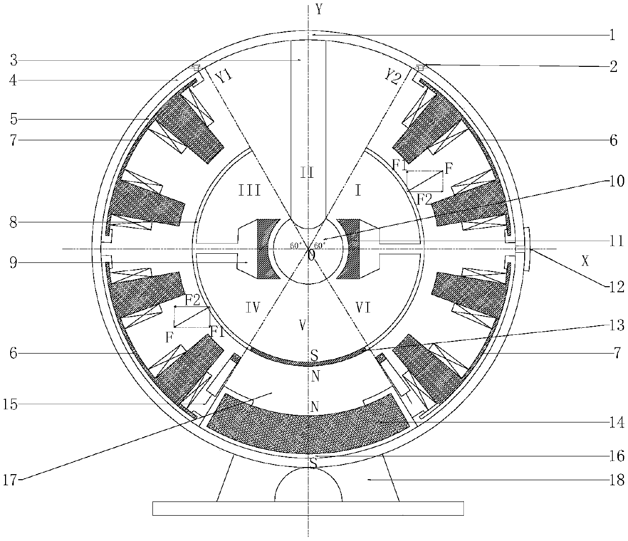
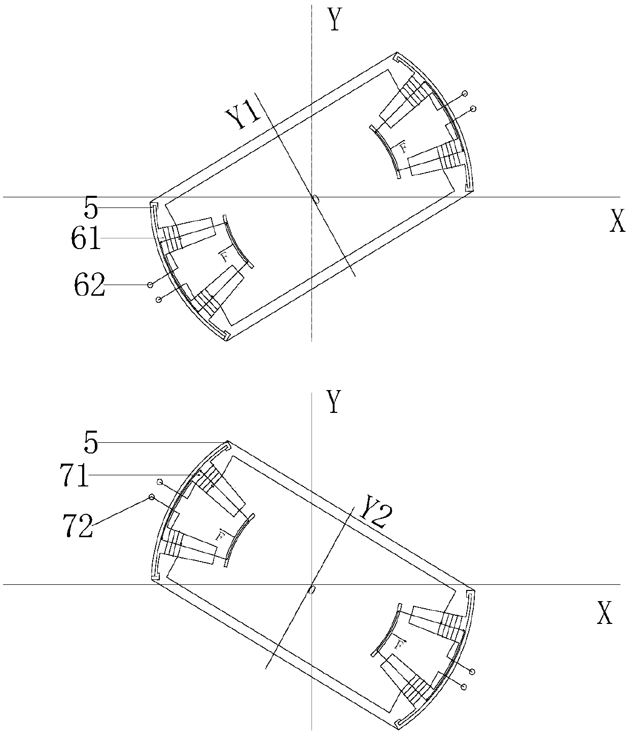
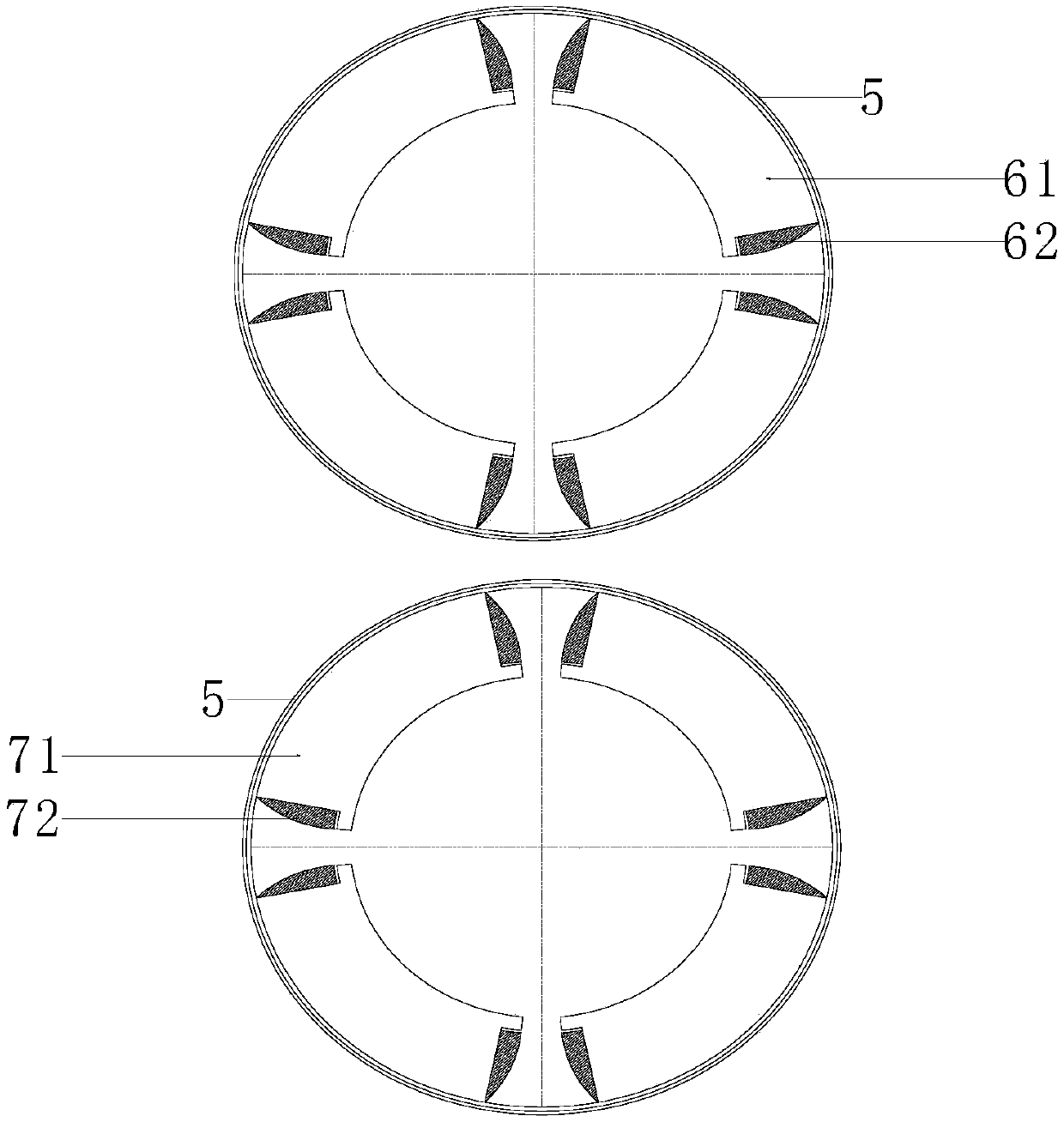
[0028] The invention provides a magnetic levitation spherical bearing with eight pairs of stator poles. The surface of each stator pole is spherical, and each pair of stator poles is divided into upper and lower spherical stator poles. The poles are respectively equipped with a bias coil and a control coil, and the bias coils of the two stator poles are connected in series, and a constant current is passed to provide a bias magnetic field for the magnetic levitation spherical bearing to work. On each pair of stator poles, another control coil is connected in series according to certain requirements, so that the magnetic flux generated by the bias coil and the control current in the control coil is added in one pair of stator poles and subtracted in the other pair of stator poles. Therefore, the air gap flux between a pair of stator poles and the spherical flywheel increases, and the air gap flux between the other pair of stator poles and the spherical flywheel decreases, accord...


PUM


Abstract

The invention discloses a control method of a spherical electric vehicle use magnetic suspended flywheel battery. In the working processing of the spherical flywheel battery, a control mode that a magnetic field laminates differential is adopted, that is, a pair of upper stator poles and a pair of lower stator poles are provided with bias coils and control coils respectively, the bias coils of the two stator poles are in series connection, and through a constant current, a bias magnetic field for a magnetic spherical faced bearing to work is provided; the control coils on each pair of the stator poles are in series connection, magnetic fluxes generated by the control coil and the control current in the control coil are added up in the pair of stator poles, and the magnetic fluxes of the control coil and the control current generated in the control coil are subtracted in the other pair of stator poles, therefore an air gap flux between the pair of the stator poles and a spherical flywheel is increased, an air gap flux between the other pair of the stator poles and the spherical flywheel is reduced, according to a formula I, B is a magnetic induction intensity, S is a stator spherical face area of the spherical faced bearing, mu0 is an air permeability, electromagnetic force bore at one side is increased, and electromagnetic force bore at the other side is reduced, therefore the position of the spherical faced flywheel is adjusted to be always at a balanced position.

Description

technical field [0001] The invention relates to the field of control of a flywheel battery (also called a flywheel energy storage device), in particular to the field of control of a vehicle-mounted spherical flywheel battery. Background technique [0002] The maglev flywheel battery is an energy storage device that converts energy between mechanical energy and electrical energy. It stores energy in the form of rotational kinetic energy of the high-speed rotating flywheel rotor and outputs it in the form of electrical energy for people to use. Compared with traditional energy storage batteries, maglev flywheel batteries have many advantages such as high energy storage density, fast charging and discharging time, high energy conversion rate, and no pollution. Therefore, the maglev flywheel battery is a new type of "green battery" with broad development prospects. [0003] At present, environmental pollution and the continuous reduction of crude oil reserves used by internal c...

Claims


Application Information

Patent Timeline
Patent Type & Authority Patents(China)
IPC IPC(8): H02K7/02H02K7/09H02N15/00
CPCH02K7/025H02K7/09H02N15/00Y02E60/16Y02T10/64
Inventor 张维煜杨恒坤朱熀秋陈涛
Owner 江苏良基集团有限公司
Why Eureka
Try Eureka