A five-degree-of-freedom hybrid magnetic bearing for a vehicle flywheel battery

A hybrid magnetic bearing and flywheel battery technology, applied in the directions of magnetic bearings, bearings, shafts and bearings, can solve the problem of large volume of the flywheel battery, and achieve the effect of simplifying the structure of the stator, reducing the volume and shortening the length.

Active Publication Date: 2019-02-05
JIANGSU UNIV
View PDF9 Cites 0 Cited by
  • Summary
  • Abstract
  • Description
  • Claims
  • Application Information

AI Technical Summary

Problems solved by technology

In this way, the length of the main shaft of the flywheel is relatively long, which will inevitably lead to the excessive volume of the flywheel battery. At the same time, the length of the main shaft of the flywheel is an important factor affecting the gyro torque on the rotating shaft

Method used


Image

  • A five-degree-of-freedom hybrid magnetic bearing for a vehicle flywheel battery
  • A five-degree-of-freedom hybrid magnetic bearing for a vehicle flywheel battery
  • A five-degree-of-freedom hybrid magnetic bearing for a vehicle flywheel battery

Examples


Embodiment Construction

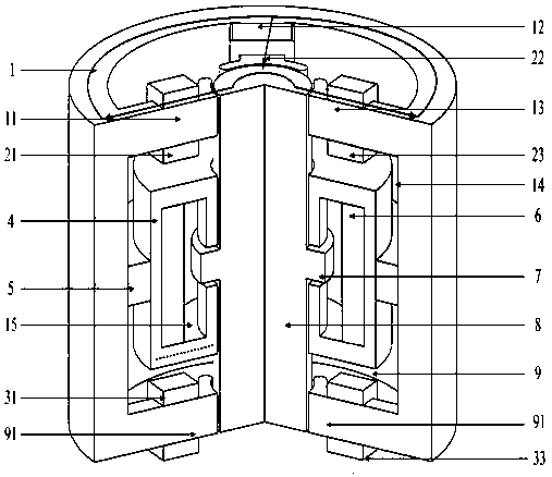
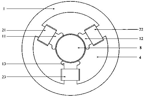
[0026] see figure 1 figure 2 Shown, the present invention is the rotor 8 in the middle, and the axial stator 4 and the radial stator are sheathed coaxially outside the rotor 8. The radial stator is composed of an upper radial stator 1 and a lower radial stator 9 , and the upper radial stator 1 and the lower radial stator 9 are coaxially arranged along the axial direction of the rotor 8 . The yokes of the upper radial stator 1 and the lower radial stator 9 are coaxially arranged up and down along the axial direction of the rotor 8, and the upper and lower yokes are connected as a whole, and the upper and lower yokes form a hollow cylinder, and the inner cavity of the hollow cylinder That is the radial stator cavity 14 .

[0027] The upper end surface of the upper radial stator 1 is flush with the upper end surface of the rotor 8 , and the lower end surface of the lower radial stator 9 is flush with the lower end surface of the rotor 8 .

[0028] In the radial stator cavity ...


PUM


Abstract

The invention discloses a five-degree-of-freedom hybrid magnetic bearing for a vehicle-mounted flywheel battery. A cylindrical rotor is coaxially sleeved with an axial stator and radial stators. The radial stators comprise the upper radial stator and the lower radial stator, wherein the upper radial stator and the lower radial stator are coaxially arranged in the axial direction, a yoke part of the upper radial stator and a yoke part of the lower radial stator are connected integrally, and a radial stator pole cavity is formed by the upper yoke part and the lower yoke part. Three radial stator poles are evenly arranged at the upper end of the yoke part of the upper radial stator in the circumferential direction, three radial stator poles are evenly arranged at the lower end of the yoke part of the lower radial stator in the circumferential direction, and a radial control coil is wound on each radial stator pole. The surface of the inner end of each radial stator pole is an arc-shaped cylindrical surface which right faces the rotor. The middle portion of the rotor is coaxially sleeved with the axial stator. An axial control coil which is closely attached to the inner wall of the axial stator and arranged outside the rotor in a sleeving mode is arranged in a cavity of the axial stator. The middle portion of the rotor is closely sleeved with a tensile plate. An axial air gap is formed between the axial stator and the tensile plate, and the middle portion of the axial stator is coaxially and closely sleeved with an annular permanent magnet. By adoption of a five-degree-of-freedom integrated structure, the length of a shaft is decreased, and the gyroscopic effect of the rotor is effectively restrained.

Description

technical field [0001] The invention belongs to the non-mechanical contact magnetic suspension bearing, and is especially suitable for the suspension support of the vehicle-mounted flywheel battery. Background technique [0002] The vehicle flywheel battery uses the magnetic levitation support and the rotational inertia of the flywheel to realize energy storage. It has the advantages of high charging efficiency, high specific energy, high specific power, small mass, and long life without pollution. Due to the limited space of electric vehicles, the volume requirements for flywheel batteries are relatively high. As the supporting part of the flywheel battery, the size of the magnetic bearing has a great influence on the volume of the flywheel battery. Journal "Mechanical Design and Manufacturing", Volume No. 1001-3997 (2007) 06-0057-03, Authors: Zhu Yuqiu, Chen Yan, Xie Zhi, Analysis of Magnetic Suspension Bearing Structure and Magnetic Circuit The control degree of freedom...

Claims


Application Information

Patent Timeline
Patent Type & Authority Patents(China)
IPC IPC(8): F16C32/04
CPCF16C32/0465F16C32/047F16C32/0491F16C2361/55F16C2380/00
Inventor 张维煜杨恒坤朱熀秋
Owner JIANGSU UNIV
Why Eureka
Try Eureka