System and method for pipeline heating

a pipeline heating and system technology, applied in the field of pipeline heating systems, can solve the problems of affecting the flow rate of fluids, affecting the efficiency of pipeline heating, so as to facilitate the transportation of fluids

Inactive Publication Date: 2010-04-29
GRANBORG BERTIL
View PDF10 Cites 26 Cited by
  • Summary
  • Abstract
  • Description
  • Claims
  • Application Information

AI Technical Summary

Benefits of technology

[0006]The present invention facilitates the transportation of a fluid within a pipeline by providing a system and method for heating the pipeline and indirectly heating the fluid flow within the pipeline.
[0010]In yet another embodiment of the present invention, a thermostat controller may be used to more accurately control the temperature of a pipe being heated. A bi-metal disc may be used to cause a switch contact to open if a upper limit temperature is reached, thereby disconnecting a power source from transformers providing current to the pipe. When the pipe has cooled to the lower temperature limit, the switch will close and the power will be once again connected to the system, thus enabling the pipe to be heated once again.

Problems solved by technology

However, the transportation of crude oil using long pipelines presents several technological obstacles that must be overcome for the transportation of the crude oil to be practical.
One significant problem is that the viscosity of the crude oil may decrease during transportation and becomes extremely more difficult to move through the pipeline.
The difficulty primarily occurs due to increased fluid friction and surface tension within the pipeline caused by a decrease in oil temperature.
However, the oil cools as it is being transported over long distances though a pipeline.
This situation is amplified with pipelines used in cold weather artic environments, the viscosity of the oil increases and transportation becomes problematic over short spans of pipeline.
Another significant problem is that the temperature change in the crude oil during transportation may cause blockage or substantial obstruction of the pipeline.
This formation and precipitation of hydrates and paraffins can significantly obstruct the fluid flow within the pipeline.
If the pipeline is completely blocked, other problems arise such as an increase in pipeline pressure, which may cause structural failure of the pipeline leading to oil leakage into the surrounding environment.
Consequently, efforts to provide an efficient, cost effective and convenient temperature control of a fluid within a transportation pipeline have not met with much success to date.

Method used


Image

  • System and method for pipeline heating
  • System and method for pipeline heating
  • System and method for pipeline heating

Examples


Embodiment Construction

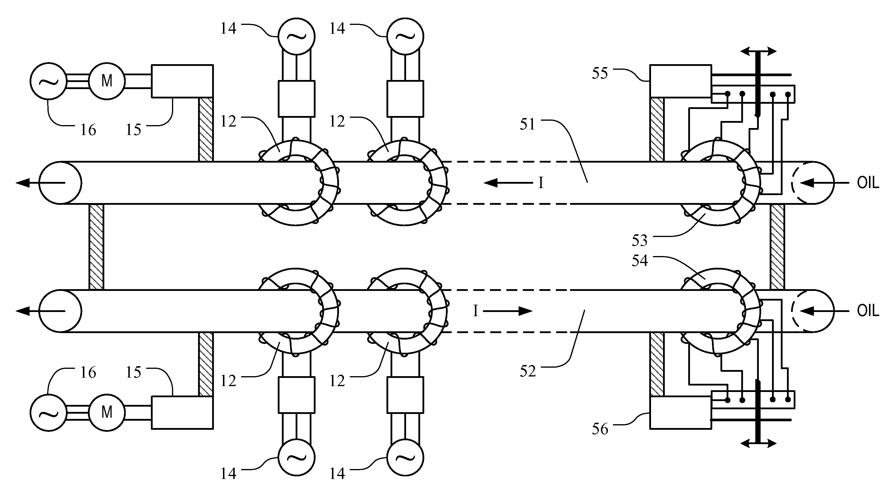
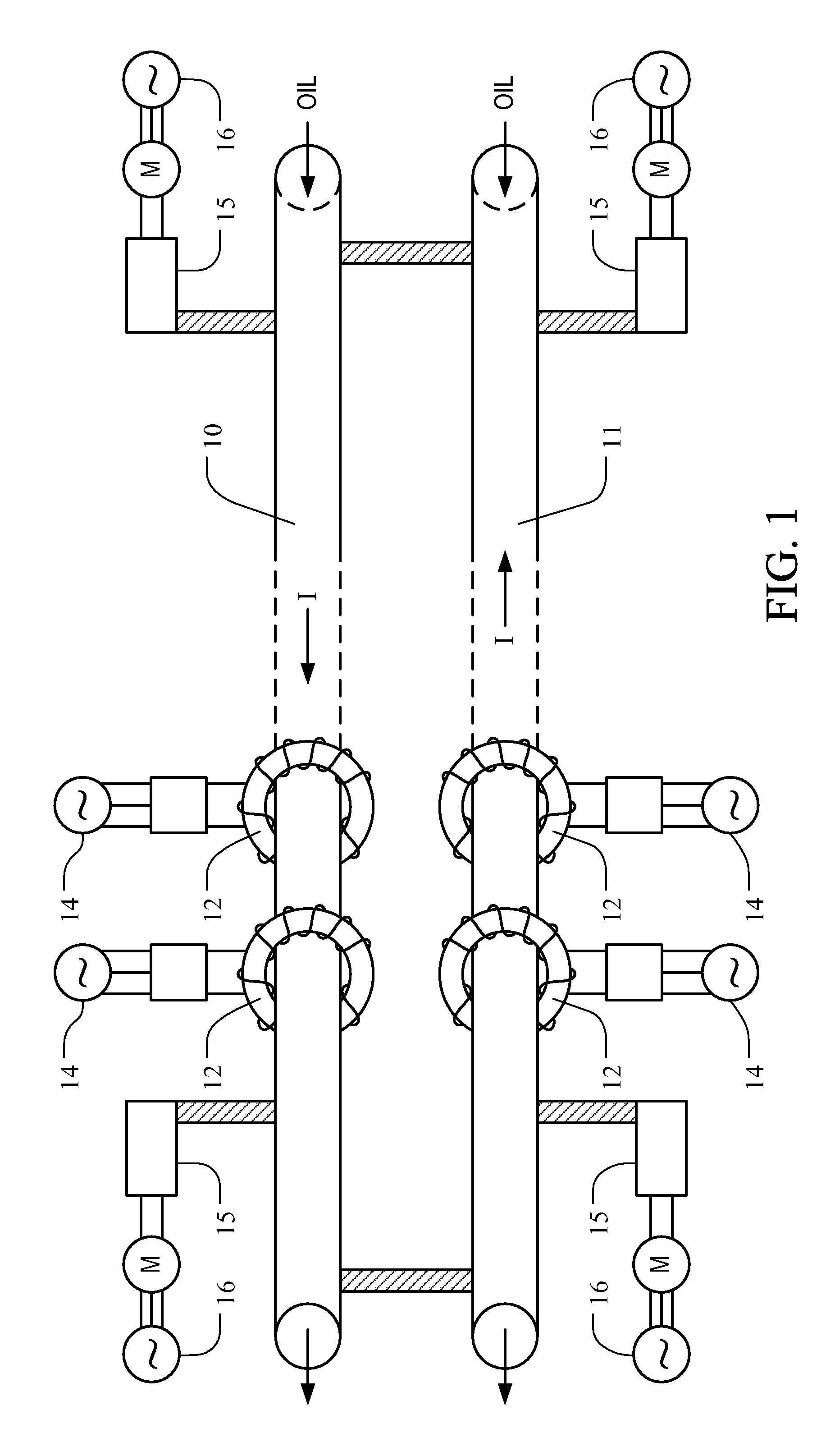
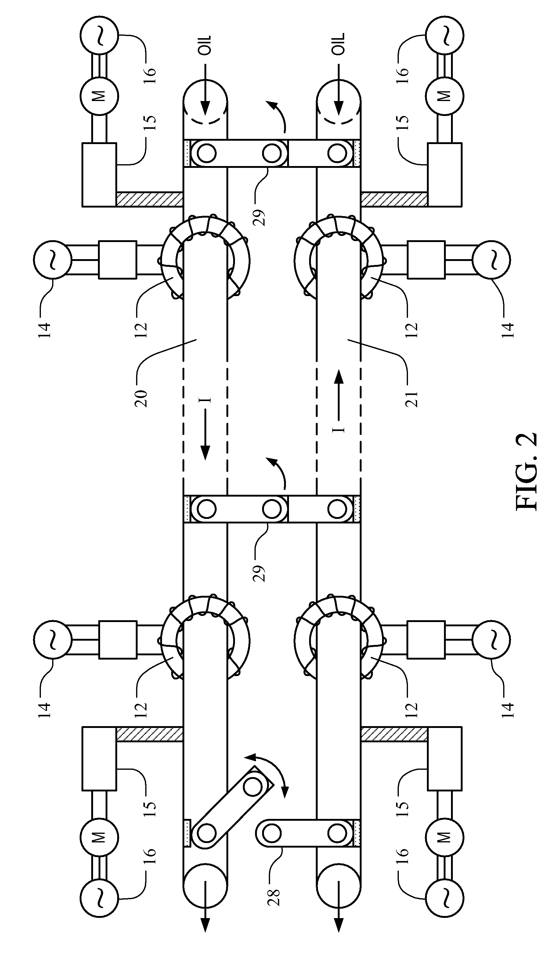
[0018]The present invention facilitates the transportation of a fluid within a pipeline by providing a system and method for heating the pipeline and indirectly heating the fluid flow therein. In the following description, numerous specific details are set forth in order to provide a more thorough description of the present invention. It will be apparent, however, to one skilled in the art, that the present invention may be practiced without these specific details. Other embodiments of the invention will readily suggest themselves to such skilled persons having the benefit of this disclosure. In some instances, well-known features have not been described in detail so as not to obscure the invention.

[0019]The present invention provides several advantages for fluid pipeline transportation systems. For example, the system and method of the present invention provides heat for a fluid flowing within the pipeline to thereby facilitate transportation of the fluid therein; the system and me...


PUM


Abstract

A fluid flow within a transportation pipeline is heated with low voltage, high current electrical energy induced into a conductive closed loop structure by one or more transformers. The closed loop structure is preferably a fluid transportation pipeline constructed of electrically conductive sections of pipeline. The amount of current induced is sufficient in relation to the inherent resistivity of the conductive sections to cause the generation of heat within the pipeline sections. By conductive and convective heat transfer, the heat induced into the pipeline structure is transferred to a fluid flow within the pipeline. The current is preferably an alternating current of frequency which causes a majority of the current to travel at or near the outer surfaces of the pipeline sections which increases the effective resistivity of the sections and heat generation therein.

Description

FIELD OF THE INVENTION[0001]The present invention relates to a system and method using inherent resistivity of electrically conductive sections of a pipeline to generate heat within the pipeline. Specifically, the present invention relates to using the generated heat within the pipeline to heat a fluid flowing therein to facilitate transportation of the fluid between one or more distant locations. More specifically, the present invention relates to using the pipeline as a power distribution line to provide auxiliary power to remote pipeline locations.BACKGROUND OF THE INVENTION[0002]Fluid transportation pipelines have long been used to deliver various fluids over long distances. One common application for a fluid transportation pipeline is an oil pipeline which is used to transport crude oil from an extraction site to a distant refinery or secondary transportation system. However, the transportation of crude oil using long pipelines presents several technological obstacles that must...

Claims


Application Information

Patent Timeline
IPC IPC(8): F16L53/00H05B6/10F16L53/34
CPCF16L53/004F16L53/34Y10T137/6606
Inventor GRANBORG, BERTIL
Owner GRANBORG BERTIL
Why Eureka
Try Eureka