Hybrid driving apparatus, vehicle with the same and control method of the same

a driving apparatus and hybrid technology, applied in the direction of electric propulsion mounting, transportation and packaging, gearing, etc., can solve the problems of limited charging, relatively performed, and output control of a main power source, and achieve the effect of avoiding the shift shock in the shift operation and a larger gear ratio

Active Publication Date: 2010-04-29
TOYOTA JIDOSHA KK
View PDF35 Cites 11 Cited by
  • Summary
  • Abstract
  • Description
  • Claims
  • Application Information

AI Technical Summary

Benefits of technology

[0021]The invention can achieve the hybrid driving apparatus provided with the power source and the electric motor, and particularly the hybrid driving apparatus that can reliably avoid the shift shock in the shift operation from a currently selected gear ratio to a larger gear ratio. Also, the invention can achieve the vehicle provided with the above hybrid driving apparatus as well as the control method thereof.

Problems solved by technology

In some cases, charging is limited in a power storage device connected electrically to a power generator.
More specifically, when the power storage device is in a state of charge of a rated value or more, the charging is limited for protecting the power storage device from overcharge.
However, output control of a main power source (e.g., an engine) is performed relatively slowly as compared with torque down control of the electric motor and power generator so that a power balance is lost in the hybrid driving apparatus.
This results in rising of the rotational speed of the main power source.
As described above, it is difficult to achieve simultaneously two mutually contradictory objects, to avoid the shift shock due to execution of the torque down of the electric motor and power generator and to keep the main power source at or below the allowed upper limit rotational speed.
In this case, it can be considered that the latter is achieved on a priority basis for preventing damages of the main power source, resulting in a problem that the shift shock cannot be avoided.

Method used


Image

  • Hybrid driving apparatus, vehicle with the same and control method of the same
  • Hybrid driving apparatus, vehicle with the same and control method of the same
  • Hybrid driving apparatus, vehicle with the same and control method of the same

Examples


Embodiment Construction

[0030]Embodiments of the invention will now be described with reference to the drawings. In the following description, the same or corresponding portions bear the same reference numbers, and description thereof is not repeated.

[0031](Structure of Hybrid Driving Apparatus)

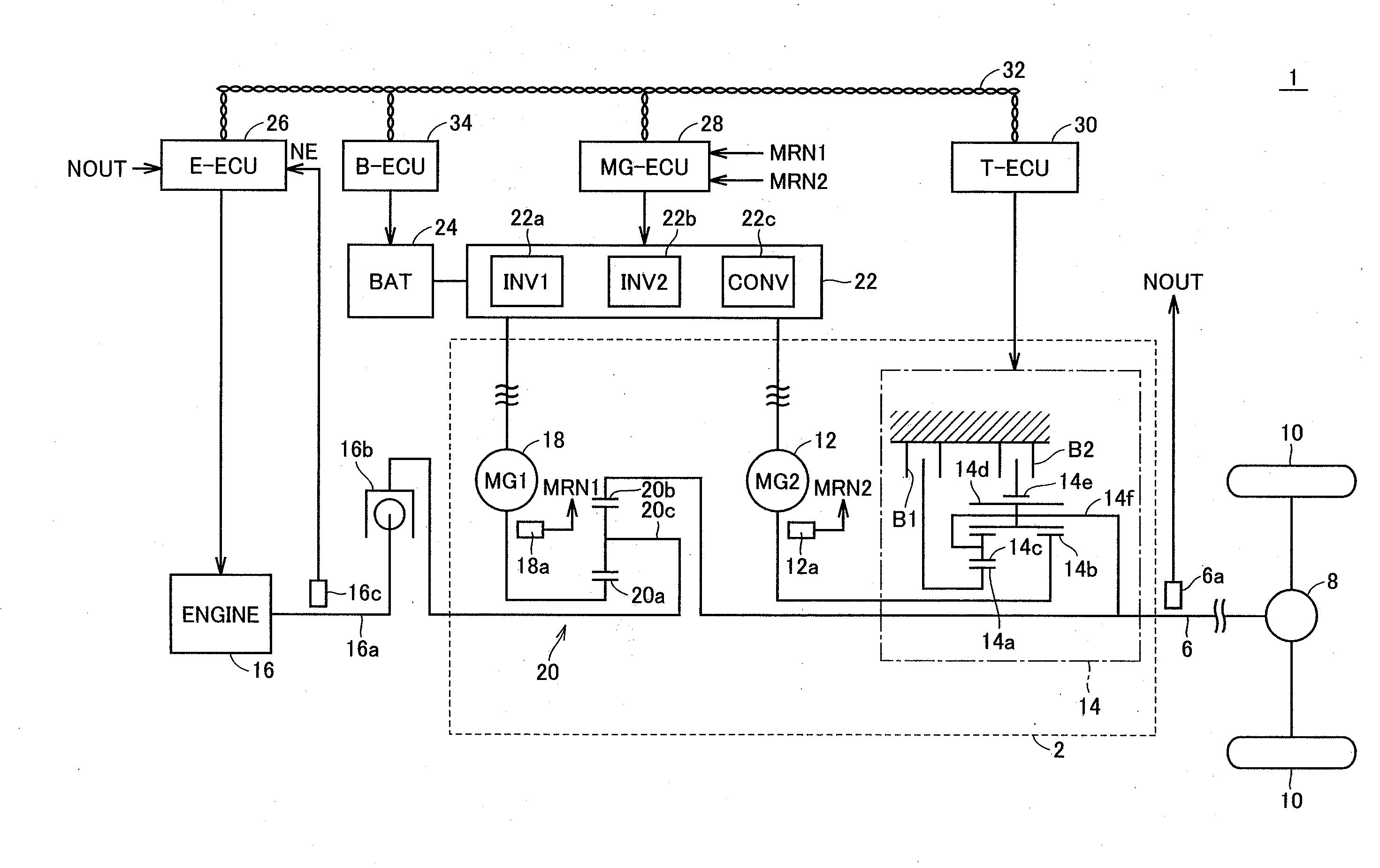
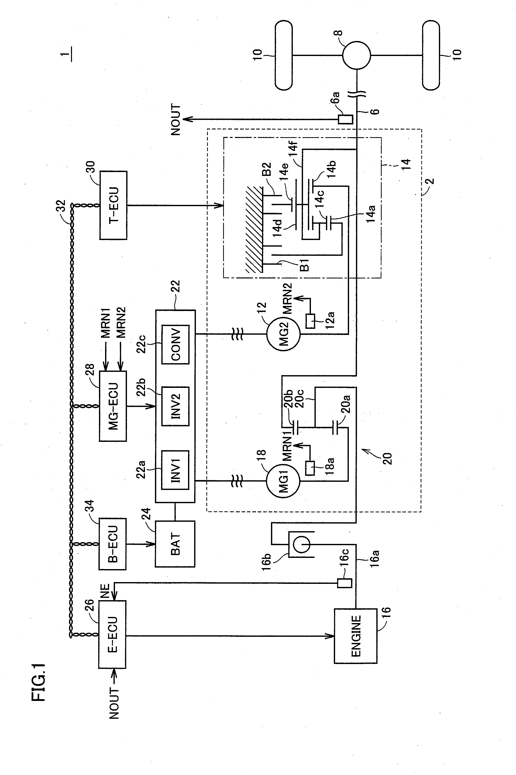
[0032]FIG. 1 shows a schematic structure of a hybrid driving apparatus 1 according to an embodiment of the invention.

[0033]Referring to FIG. 1, hybrid driving apparatus 1 according to the embodiment of the invention includes an engine 16 corresponding to a “power source”, a transaxle 2, a rotation output shaft 6, a differential gear 8 and drive wheels 10.

[0034]The output torque of engine 16 is transmitted to rotation output shaft 6 via transaxle 2, and is further transmitted therefrom to drive wheels 10 via differential gear 8. Transaxle 2 can operate to generate an electric power by receiving a part of an output torque of engine 16, and also to perform selectively power running control for adding a drive power for ...


PUM


Abstract

For raising an MG2 rotational speed MRN2 to a target rotational speed (low-gear rotational speed NLG), an output torque of an MG2 starts to increase at a time t4. During an inertia phase (period α), the output torque of the MG2 is limited not to exceed a first limit value TLIM1 determined according to a shift progress degree PRG and a second limit value TLIM2 determined according to a rotational speed margin NEmgn. Since the output torque of the MG2 is sufficiently small in a final stage of the inertia phase (period α), output variations occurring at a time t6 when torque down is performed on the MG2 can be small. The torque down of the MG1 and MG2 does not raise engine rotational speed NE.

Description

TECHNICAL FIELD[0001]The invention relates to a hybrid driving apparatus provided with a power source and an electric motor, a vehicle with the same and a control method of the same, and particularly to a structure in which the electric motor is mechanically connected to a rotation output shaft via a transmission mechanism capable of selecting a plurality of gear ratios.BACKGROUND ART[0002]Japanese Patent Laying-Open No. 2004-203219 has disclosed a hybrid driving apparatus in which an electric motor allowing control of a rotational speed is connected to an output member receiving a torque supplied from a main power source via a transmission mechanism performing shifting by changing an engagement device between engaged and released states.[0003]This hybrid driving apparatus controls the electric motor to attain a specific target rotational speed during power-off shifting so that a shifting delay and / or a shifting shock may be prevented at the time of power-off shifting.[0004]Japanese...

Claims


Application Information

Patent Timeline
Patent Type & Authority Applications(United States)
IPC IPC(8): B60W20/00B60W10/08B60W10/10B60K6/365B60K6/445B60K6/547B60L50/16B60W10/26F16H59/42F16H59/72F16H61/04F16H61/68F16H61/684F16H61/686F16H63/40F16H63/50
CPCB60K1/02Y10T477/23B60K6/445B60K6/547B60L2240/421B60L2240/423B60L2240/441B60W10/08B60W10/115B60W20/00B60W30/19B60W2510/0638B60W2510/081B60W2510/244B60W2710/083F16H61/0437F16H63/502F16H2037/0873F16H2061/6603Y02T10/6239Y02T10/642B60K6/365Y02T10/62Y02T10/64B60W2510/1065B60W10/11B60W20/10
Inventor SUZUKI, YOSHITAKAMURATA, KEIICHI
Owner TOYOTA JIDOSHA KK
Why Eureka
Try Eureka