Wingless Hovering Of Micro Air Vehicle

a micro-air vehicle and wingless technology, applied in the direction of machines/engines, vertical landing/take-off aircraft, airflow influencers, etc., can solve the problems of unsteady magnitude of lift force, serious limitation of the hovering capability of a mav using a flapping rigid wing, and easy disruption of lift generated by rigid flapping wings, so as to reduce the load from wind, reduce the effect of lift to drag ratio and degradation of airfoil efficiency

Active Publication Date: 2010-04-29
UNIV OF FLORIDA RES FOUNDATION INC
View PDF29 Cites 9 Cited by
  • Summary
  • Abstract
  • Description
  • Claims
  • Application Information

AI Technical Summary

Benefits of technology

[0008]Additional embodiments can allow active response to the surrounding flow conditions. The issue of low lift to drag ratio and degradation of airfoil efficiency due to the inability of laminar boundary layers attachment can also be significantly reduced, or eliminated. The electromagnetic force can be generated by applying a pulsed (alternating/rf) voltage between a set of grounded and powered electrodes separated by a polymer insulator, dielectric, or other material with insulating properties. DC currents applied to such electrodes can also be utilized to provide the force. In a specific embodiment, a permanent magnet, or other source of magnetic field such as an electromagnet can be used to create a magnetic field in the device so as to create a selective bias force on a current carrying conductor (J×B). The current in the conductor and/or strength of the B field can be altered to adjust the force.
[0009]While the physical weight of the subject wingless WHOMAV design can be similar to the weight of traditional winged micro air vehicles (MAVs), embodiments of

Problems solved by technology

The magnitude of this lift force is, however, unsteady.
While the flapping wing theoretically mimics insects and birds in nature, the lift generated due to rigid flapping wings may be easily disrupted with the rup

Method used


Image

  • Wingless Hovering Of Micro Air Vehicle
  • Wingless Hovering Of Micro Air Vehicle
  • Wingless Hovering Of Micro Air Vehicle

Examples


Embodiment Construction

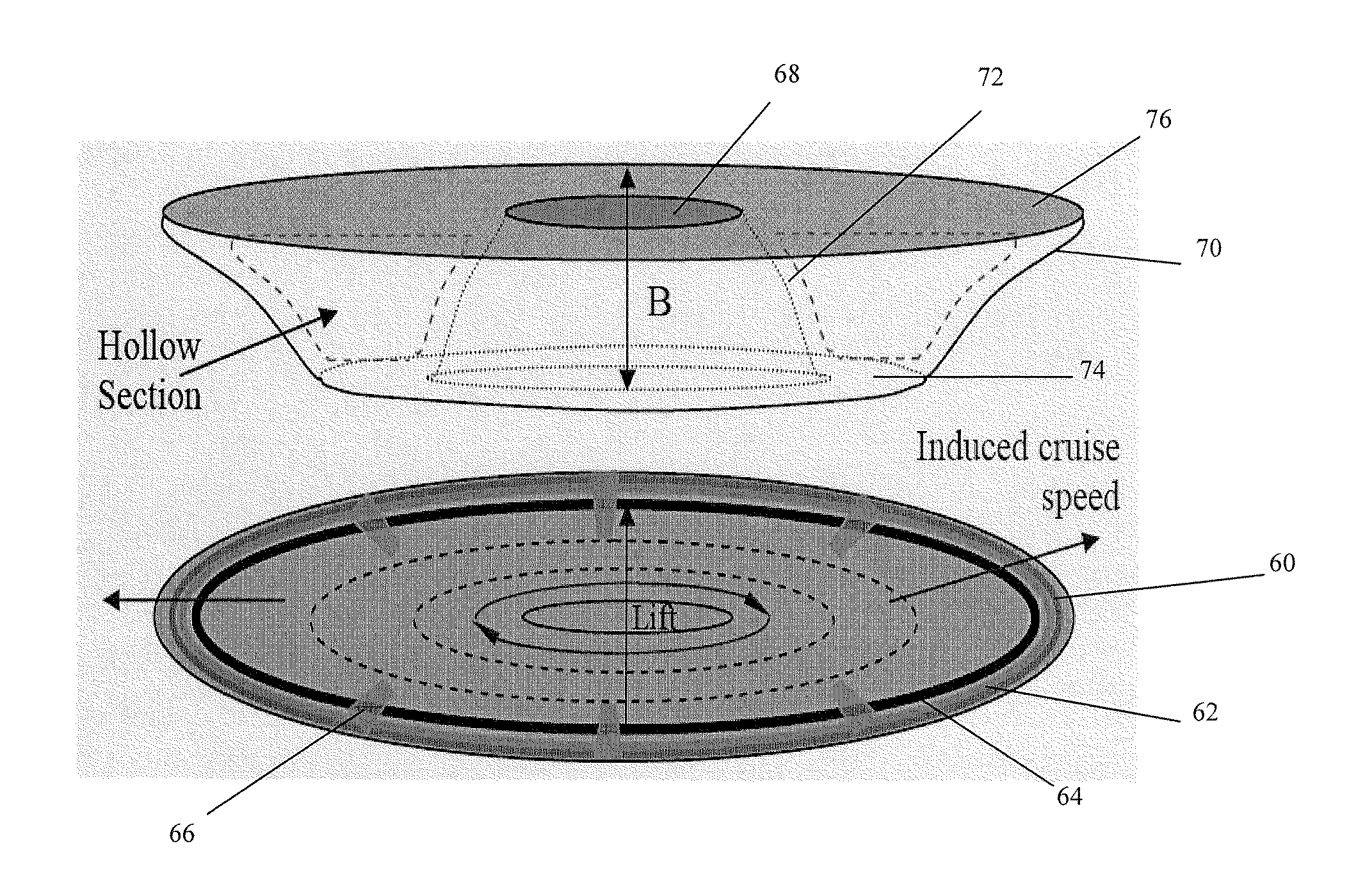
[0033]Embodiments of the subject invention relate to a Wingless Hovering Micro Air Vehicle (WHOMAV). Embodiments of the WHOMAV can incorporate a Power Source Unit (PSU), which can include, for example, batteries, or other appropriate power sources known in the art. Embodiments can operate at reasonable power levels for hovering and withstanding expected wind gusts. Embodiments of the subject invention can have a diameter less than 15 cm. Embodiments can have one or more smooth (continuous curvature) surface and can be operated using electromagnetic and / or electrohydrodynamic principles. The wingless design of specific embodiments can allow operation with no rotating or moving components. Additional embodiments can allow active response to the surrounding flow conditions. The issue of low lift to drag ratio and degradation of airfoil efficiency due to the inability of laminar boundary layers attachment can also be significantly reduced, or eliminated. The electromagnetic force can be...


PUM


Abstract

Embodiments of the subject invention relate to a Wingless Hovering Micro Air Vehicle (WHOMAV) and its Power Source Unit (PSU). Embodiments can operate at reasonable power levels for hovering and withstanding expected wind gusts. Embodiments of the subject invention can have a diameter less than 15 cm. Embodiments can have one or more smooth (continuous curvature) surface and can be operated using electromagnetic and electrohydrodynamic principles. The wingless design of specific embodiments can allow operation with no rotating or moving components. Additional embodiments can allow active response to the surrounding flow conditions. The issue of low lift to drag ratio and degradation of airfoil efficiency due to the inability of laminar boundary layers attachment can also be significantly reduced, or eliminated. The electromagnetic force can be generated by applying a pulsed (alternating/rf) voltage between a set of grounded and powered electrodes separated by a polymer insulator, dielectric, or other material with insulating properties.

Description

CROSS-REFERENCE TO RELATED APPLICATIONS[0001]This application is a continuation-in-part of International Patent Application No. PCT / 2007 / 074874, filed Jul. 31, 2007, which claims the benefit of U.S. Application Ser. No. 60 / 928,207, filed May 8, 2007, and claims the benefit of U.S. Application Ser. No. 60 / 834,265, filed Jul. 31, 2006, the disclosures of which are hereby incorporated by reference herein in their entirety, including any figures, tables, or drawings.BACKGROUND OF INVENTION[0002]Typical unmanned aerial vehicles (UAVs) are less than 15 cm with wingspan. In traditional winged MAVs, the control surfaces are open to the wind and thus very sensitive to wind gusts, at speeds comparable to vehicle flight speeds.[0003]The traditional lift generation mechanism in a micro air vehicle (MAV), is shown in FIG. 1A. Referring to the top of FIG. 1A, air moves over the wing surface with no separation such that the conventional airfoil produces a steady state standing vortex trailing the ...

Claims


Application Information

Patent Timeline
IPC IPC(8): B64C39/00B64C29/00H05H1/46
CPCB64C39/028B64C2201/027B64C2201/042B64C2230/12Y02T50/166B64C39/00B64C39/001F05D2270/172Y02T50/10H05H1/2439B64U10/13B64U50/19
Inventor ROY, SUBRATA
Owner UNIV OF FLORIDA RES FOUNDATION INC
Why Eureka
Try Eureka