Controlled power supply and method for pulse load

a power supply and pulse load technology, applied in the direction of power conversion systems, dc-dc conversion, instruments, etc., can solve the problems of reducing the current delivery capability of the supply source, and reducing the filter size. , to achieve the effect of reducing the size of the filter

Active Publication Date: 2010-04-29
ELTA SYST LTD
View PDF4 Cites 9 Cited by
  • Summary
  • Abstract
  • Description
  • Claims
  • Application Information

AI Technical Summary

Benefits of technology

[0014]It is an object of the invention to provide a power supply fo

Problems solved by technology

Owing to the sharp changes in the current requirement when the switch is on or off, the ripple current in the current supplied by the main power supply can cause high radio frequency interference RFI which is reflected on to the main supply source if it is not suppressed.
Maintaining the ripple current as low as possible also diminishes the conduction losses related to high root mean square (RMS) cu

Method used


Image

  • Controlled power supply and method for pulse load
  • Controlled power supply and method for pulse load
  • Controlled power supply and method for pulse load

Examples


Embodiment Construction

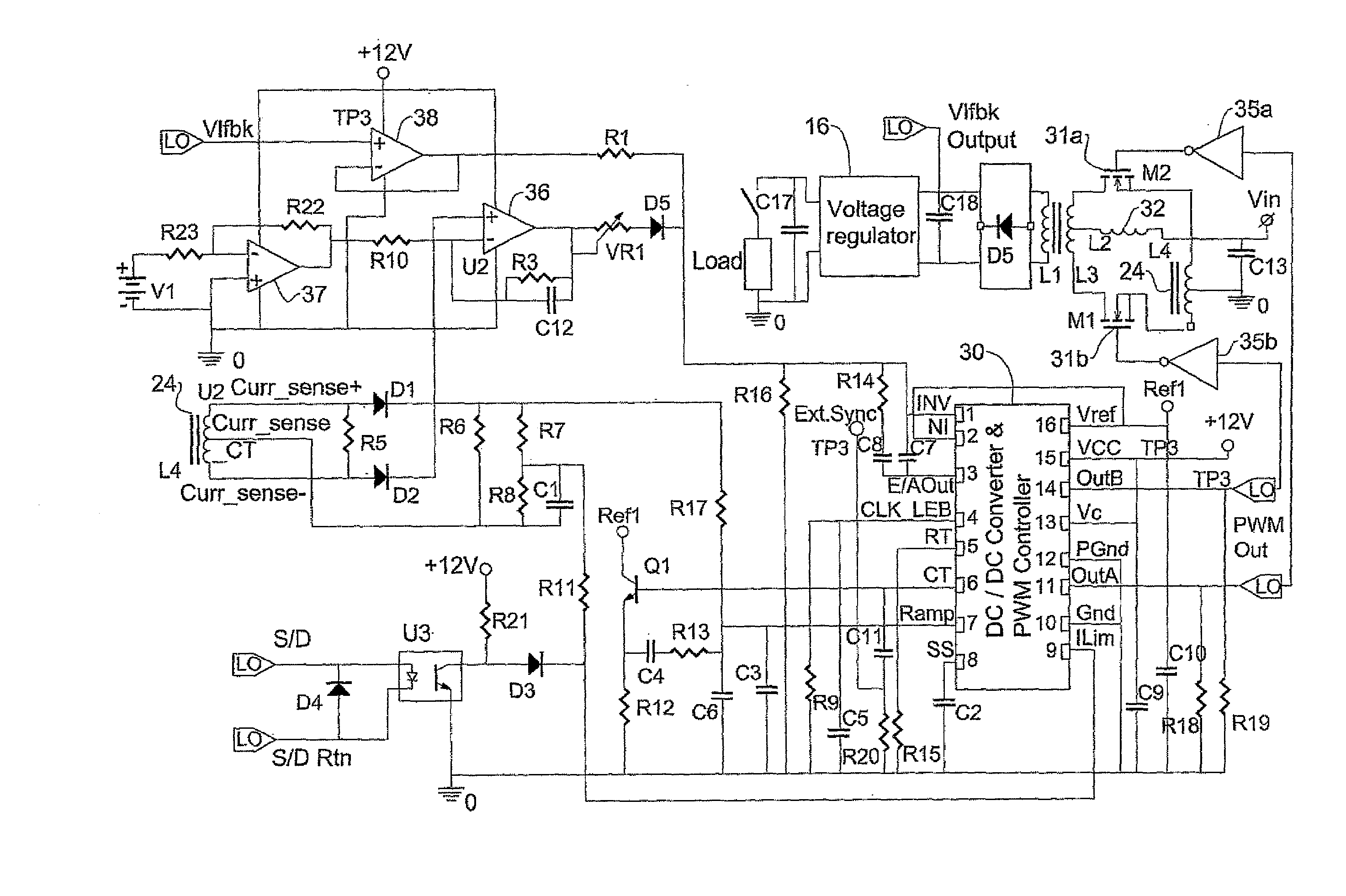
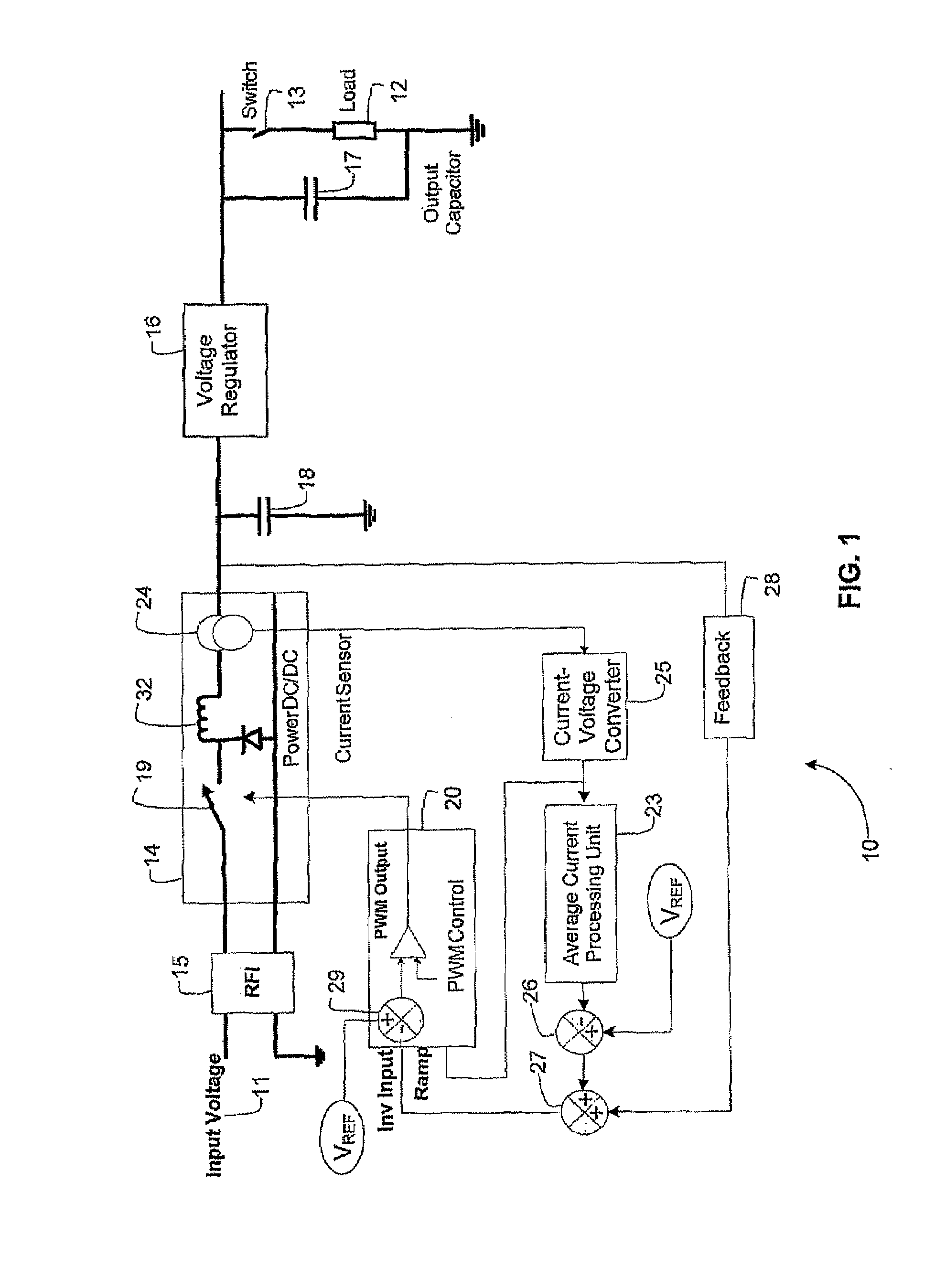
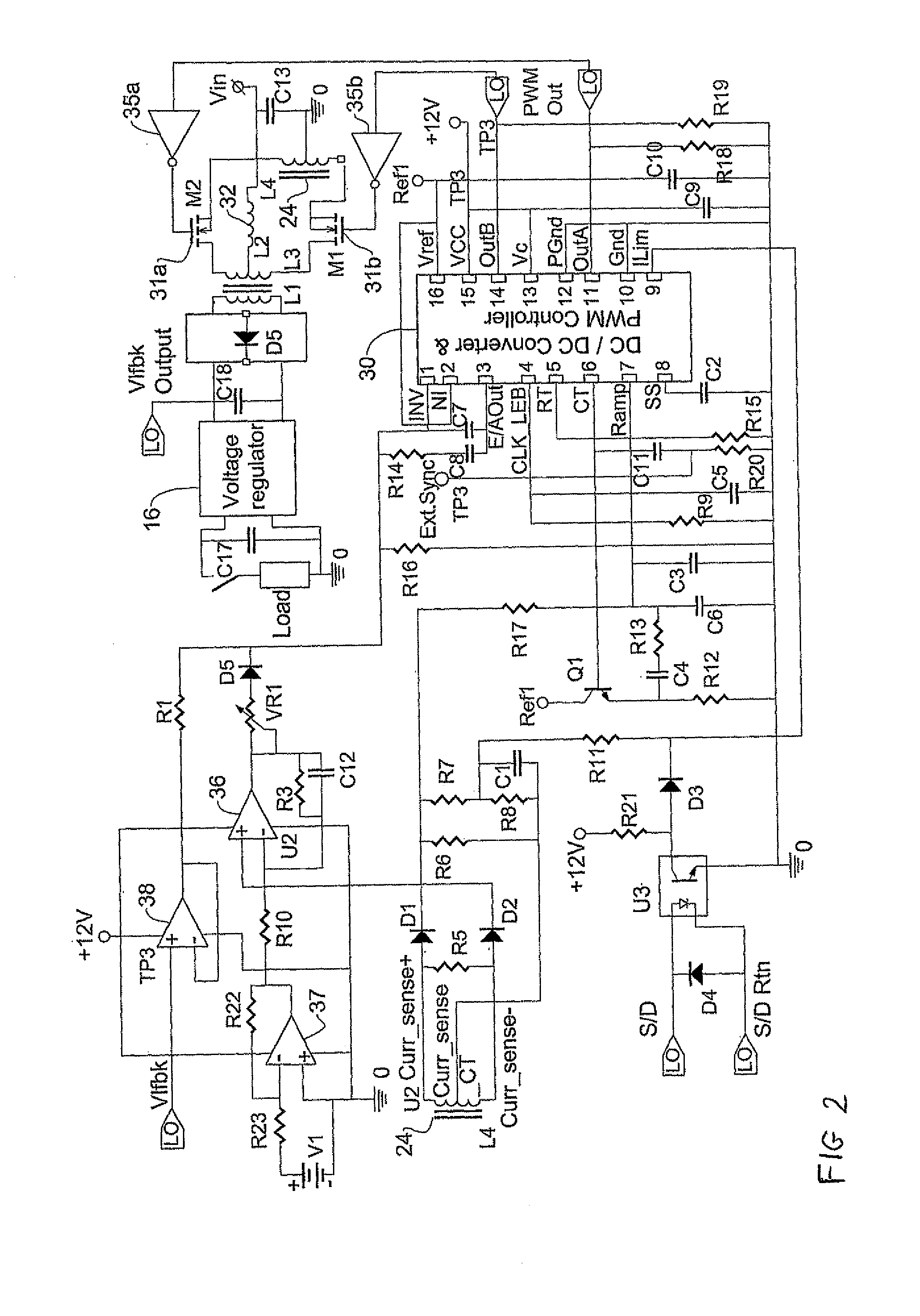
[0030]FIG. 1 illustrates a controlled power supply 10 for supplying bursts of substantially constant voltage from a voltage source 11 to a switched load 12 via a controlled load switch 13, in accordance with an embodiment of the present invention. The voltage source 11 may, for example, be a rectified phase of a 3-phase power line having a rectified line voltage. It could equally well be a bank of batteries configured to provide a required line voltage. An input of a DC / DC converter 14 (constituting a switching converter) is connected to the voltage source 11 via an optional input filter 15. An output of the DC / DC converter 14 is connected to a voltage regulator 16 whose output is connected to an output capacitor 17 connected across the switched load 12. The DC / DC converter 14 includes as part of its output a voltage reservoir for storing voltage, which for the sake of explanation is shown as a storage capacitor 18 that is external to the DC / DC converter 14. The DC / DC converter 14 m...


PUM


Abstract

A method for supplying bursts of substantially constant voltage to a switched load via a voltage reservoir. Based on a predetermined current that is to be sourced by the load during an active portion of a switching cycle, computing an average current that should be fed to the voltage reservoir during an inactive portion of the switching cycle to ensure that sufficient energy will stored in the voltage reservoir to supply the load without completely draining the voltage reservoir. Supplying continuous energy to the voltage reservoir at a substantially constant current equal in magnitude to said average current.

Description

FIELD OF THE INVENTION[0001]This invention relates to pulse load switching power supplies.BACKGROUND OF THE INVENTION[0002]A pulsed load or switched load is a load which requires a large supply of power intermittently. A switching mode power supply for such a load includes a switch that operates at a low frequency to allow high amplitude current to be supplied intermittently to the load. The switch “chops” a low voltage input DC source, thus converting it to a high-ripple pulsed AC voltage, which is transformed to an interface voltage that may then be used directly or rectified and smoothed to produce DC voltage, according to the application. Ripple current refers to the variation in the DC signal. Owing to the sharp changes in the current requirement when the switch is on or off, the ripple current in the current supplied by the main power supply can cause high radio frequency interference RFI which is reflected on to the main supply source if it is not suppressed.[0003]The circuit...

Claims


Application Information

Patent Timeline
IPC IPC(8): G05F1/10
CPCH02M3/1582H02M3/158
Inventor ZELIG, ROBERTBATIKOFF, ENRIQUE
Owner ELTA SYST LTD
Why Eureka
Try Eureka