
Fabric type input device

a technology of input device and fabric, which is applied in the direction of identification means, instruments, mobile visual advertising, etc., can solve the problems of user inconvenience such as foreign body feeling, user may provoke a foreign body feeling from the conventional input device, and the inconvenient separation of the conventional input device from the user's clothes, so as to achieve the effect of minimizing foreign body feeling

Inactive Publication Date: 2010-04-29
KOREA ADVANCED INST OF SCI & TECH
View PDF23 Cites 127 Cited by
  • Summary
  • Abstract
  • Description
  • Claims
  • Application Information

AI Technical Summary

Benefits of technology

[0007]The present invention is conceived to solve the aforementioned problems. Accordingly, an object of the present invention is to provide a digital input device which can minimize foreign-body feeling and be washable.
[0036]A fabric type input device according to embodiments of the present invention is manufactured using a fabric patterned with a conductive material, a conductive fiber for electrical connection, so that foreign-body feeling can be minimized. Further, the fabric type input device is washable without separating the fabric type input device from clothes.

Problems solved by technology

For this reason, when the input device is adhered to or inserted into the clothes, user's inconvenience such as foreign-body feeling may be caused.
Accordingly, when a user wears clothes to which the conventional input device is adhered, the user may provoke a foreign-body feeling from the conventional input device.
Further, it is inconvenient that the conventional input device should be separated from the user's clothes when the user washes the clothes to which the conventional input device is adhered.

Method used


Image

  • Fabric type input device
  • Fabric type input device
  • Fabric type input device

Examples


first embodiment

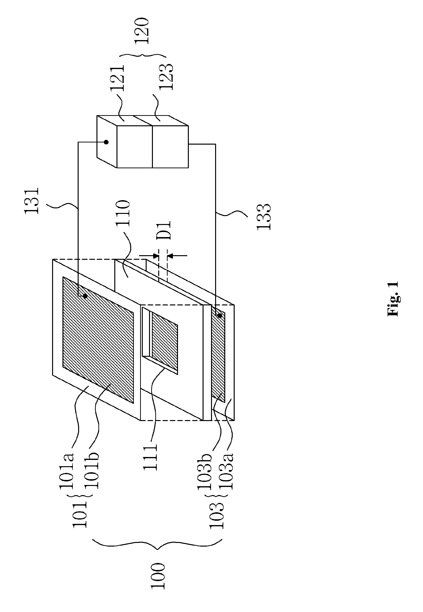
[0044]FIG. 1 is a drawing illustrating a fabric type input device using a switch mode according to a first embodiment of the present invention.

[0045]Referring to FIG. 1, the fabric type input device according to the first embodiment of the present invention comprises a fabric type electrode unit 100, a fabric type substrate unit 110 and a control unit 120.

[0046]The fabric type electrode unit 100 comprises a first fabric type electrode 101 and a second fabric type electrode 103 opposite to each other at a predetermined spacing distance D1. The first fabric type electrode 101 comprises a fabric 101a and a lead pattern 101b formed by patterning a conductive material on the fabric 101a. The second fabric type electrode 103 comprises a fabric 103a and a lead pattern 103b having a conductive material patterned on the fabric 103a. The lead patterns 101b and 103b formed in the first and second fabric type electrodes 101 and 103 may be formed by depositing or coating a conductive material on...

second embodiment

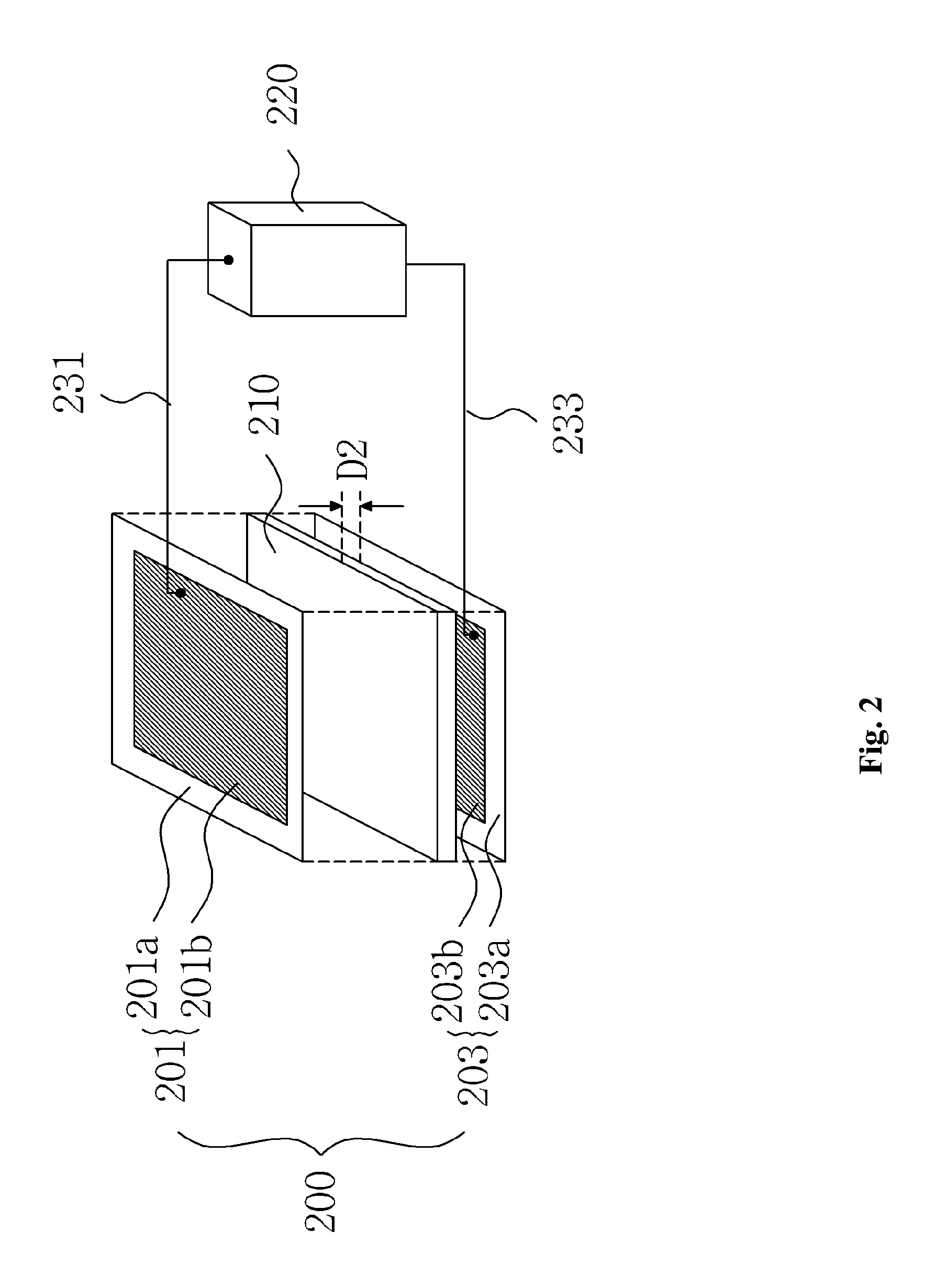
[0050]FIG. 2 is a drawing illustrating a fabric type input device using a capacitance variation sensing mode according to a second embodiment of the present invention.

[0051]Referring to FIG. 2, the fabric type input device according to the second embodiment of the present invention comprises a fabric type electrode unit 200, an elastic unit 210 and a sensor 220.

[0052]The fabric type electrode unit 200 comprises first and second fabric type electrodes 201 and 203 formed opposite to each other. The first fabric type electrode 201 comprises a fabric 201a, a lead pattern 201b having a conductive material patterned on the fabric 201a. The second fabric type electrode 203 comprises a fabric 203a and a lead pattern 203b having a conductive material patterned on the fabric 203a. The first and second fabric type electrodes 201 and 203 constitute a capacitor having the two lead patterns 201b and 203b as electrode layers. The lead patterns 201b and 203b formed in the first and second fabric ty...

third embodiment

[0056]FIG. 3 is a drawing illustrating a fabric type input device using a capacitance variation sensing mode according to a third embodiment of the present invention.

[0057]Referring to FIG. 3, the fabric type input device according to the third embodiment of the present invention comprises a fabric type electrode unit 300 and a sensor 310.

[0058]The fabric type electrode unit 300 comprises a fabric 301, first and second lead patterns 303 and 305 formed by patterning a conductive material on the fabric 301. As shown in FIG. 3, the first and second lead patterns 303 and 305 may be patterned in an interdigital form. The first and second lead patterns 303 and 305 may be formed by depositing or coating a conductive material on the fabric 301 using a mask. The conductive material may comprise silver, polymer, polyester and cyclohexanone. When the fabric type electrode unit 300 is in contact with a user's finger or the like, capacitance between the first and second lead patterns 303 and 305...


PUM


Abstract

There is a fabric type input device. The fabric type input device comprise a fabric type electrode unit comprising first and second fabric type electrodes formed opposite to each other, the first and second fabric type electrodes each comprising a fabric and a lead pattern formed by patterning a conductive material on the fabric, a fabric type substrate unit interposed between the first and second fabric type electrodes so that the first and second fabric type electrodes are spaced apart from each other, the fabric type substrate unit having a connection hole formed so that the first and second fabric type electrodes are in contact with each other and a control unit supplying an input signal to the fabric type electrode unit, the control unit sensing the supplied input signal. The fabric type input device is formed using a fabric patterned with a conductive material, thereby minimizing foreign-body feeling.

Description

CROSS-REFERENCE TO RELATED APPLICATION[0001]This application claims priority from Korean Patent Application No. 10-2008-0037353, filed on Apr. 22, 2008, the disclosure of which is hereby incorporated herein by reference in its entirety as if set forth fully herein.BACKGROUND OF INVENTION[0002]1. Field of the Invention[0003]The present invention relates to a fabric type input device.[0004]2. Discussion of the Related Art[0005]Recently, as the use of electronic devices such as notebook computers, Personal digital assistants (PDAs) and mobile terminals has increased, keyboards used as input devices of portable electronic devices have also been manufactured and come into the market. Generally, a portable keyboard is formed of a silicon material so that a user can carry the portable keyboard which is rolled up or adhered to user's clothes. However, an input device such as a portable keyboard formed of a silicon material is formed of a material completely different from that of clothes. F...

Claims


Application Information

Patent Timeline
Patent Type & Authority Applications(United States)
IPC IPC(8): G06F3/02
CPCH01H13/704H01H2203/02H01H2203/0085G02F1/1335G02F1/1343G09F21/00G09F9/37
Inventor YOO, HOI-JUNKIM, YONGSANGKIM, HYEJUNG
Owner KOREA ADVANCED INST OF SCI & TECH
Learn More