Driving circuit for fluid jet head, driving method for fluid jet head, and fluid jet printing apparatus

a technology of driving circuit and fluid jet head, which is applied in the direction of printing, electrical equipment, ac network circuit arrangement, etc., can solve the problems of large circuit, large power loss, and further lowering of power efficiency, so as to reduce the effect of operating environment, stable supply of driving voltage waveform, and sufficient reserve capacity

Active Publication Date: 2010-04-29
SEIKO EPSON CORP
View PDF5 Cites 10 Cited by
  • Summary
  • Abstract
  • Description
  • Claims
  • Application Information

AI Technical Summary

Benefits of technology

[0026]The plurality of ejection nozzles are provided on the ejection head, and there may be cases where all, some or none of the ejection nozzles are driven simultaneously. From this reason, the operating environment of the driving circuit which supplies the driving voltage waveform to the ejection head fluctuates depending on the state of usage of the ejection head. In order to reduce the effect of the operating environment to enable a stable supply of the driving voltage waveform, it is necessary to secure a sufficient reserve capacity in the driving circuit, resulting in complication or upsizing of the driving circuit. In contrast, by connecting the load which is capable of storing the electric power from an external power source parallel to the ejection head, even though the state of usage of the ejection head fluctuates, the operating environment of the driving circuit which supplies the driving voltage waveform does not fluctuate significantly. Therefore, it is not necessary to secure the reserve capacity in the driving circuit, and hence the constantly stable driving voltage waveform can be supplied without the complication or the upsizing of the driving circuit.
[0027]The capacity of the load connected in parallel to the ejection head may be configured to be changeable according to the state of usage of the ejection head. For example, it is also possible to increase the capacity of the load with decrease of the number of the ejection nozzles to be driven or decrease the capacity of the load with increase of the number of the ejection nozzles to be driven. In this manner, by changing the capacity of the load so as to cancel the fluctuation of the load capacity of the ejection head, the fluctuation of the load for the driving circuit can be reduced. Consequently, the ejection head can be driven using the stable driving voltage waveform while downsizing the driving circuit.

Problems solved by technology

However, when an attempt is made to apply the trapezoidal-shaped driving waveform in order to discharge the fluid of an accurate amount at the high repetition frequency, the following problems arise.
In a step of generating the driving voltage waveform to be applied, there is a problem such that a large power loss occurs in order to generate a voltage waveform which changes in a sloped manner at the rising or the lowering portion of the waveform.
When the actuator includes a capacity component as in the case of the piezoelectric element, there is also a problem such that a reactive power for charging and discharging electricity with respect to the capacity components of the actuator is consumed on the side of the driving voltage waveform generating circuit, and hence the power efficiency is further lowered.
Furthermore, since the dissipated power is transformed into heat, it is required to release heat from the driving voltage waveform generating circuit, resulting in a larger circuit.
When a trapezoidal driving voltage waveform is applied to the ejection head for discharging the fluid of an adequate amount at a high repetitive frequency, a large power loss occurs on the side of the circuit which generates the driving voltage waveform and, in addition, the apparatus needs to be made larger as a result of the heat-releasing measure taken in association with the power loss.
In order to reduce the effect of the operating environment to enable a stable supply of the driving voltage waveform, it is necessary to secure a sufficient reserve capacity in the driving circuit, resulting in complication or upsizing of the driving circuit.

Method used


Image

  • Driving circuit for fluid jet head, driving method for fluid jet head, and fluid jet printing apparatus
  • Driving circuit for fluid jet head, driving method for fluid jet head, and fluid jet printing apparatus
  • Driving circuit for fluid jet head, driving method for fluid jet head, and fluid jet printing apparatus

Examples


first embodiment

B. First Embodiment

Embodiment in which an Effect of an Operational Potential Difference Reduction

B-1. Configuration of Ejection Head Driving Circuit

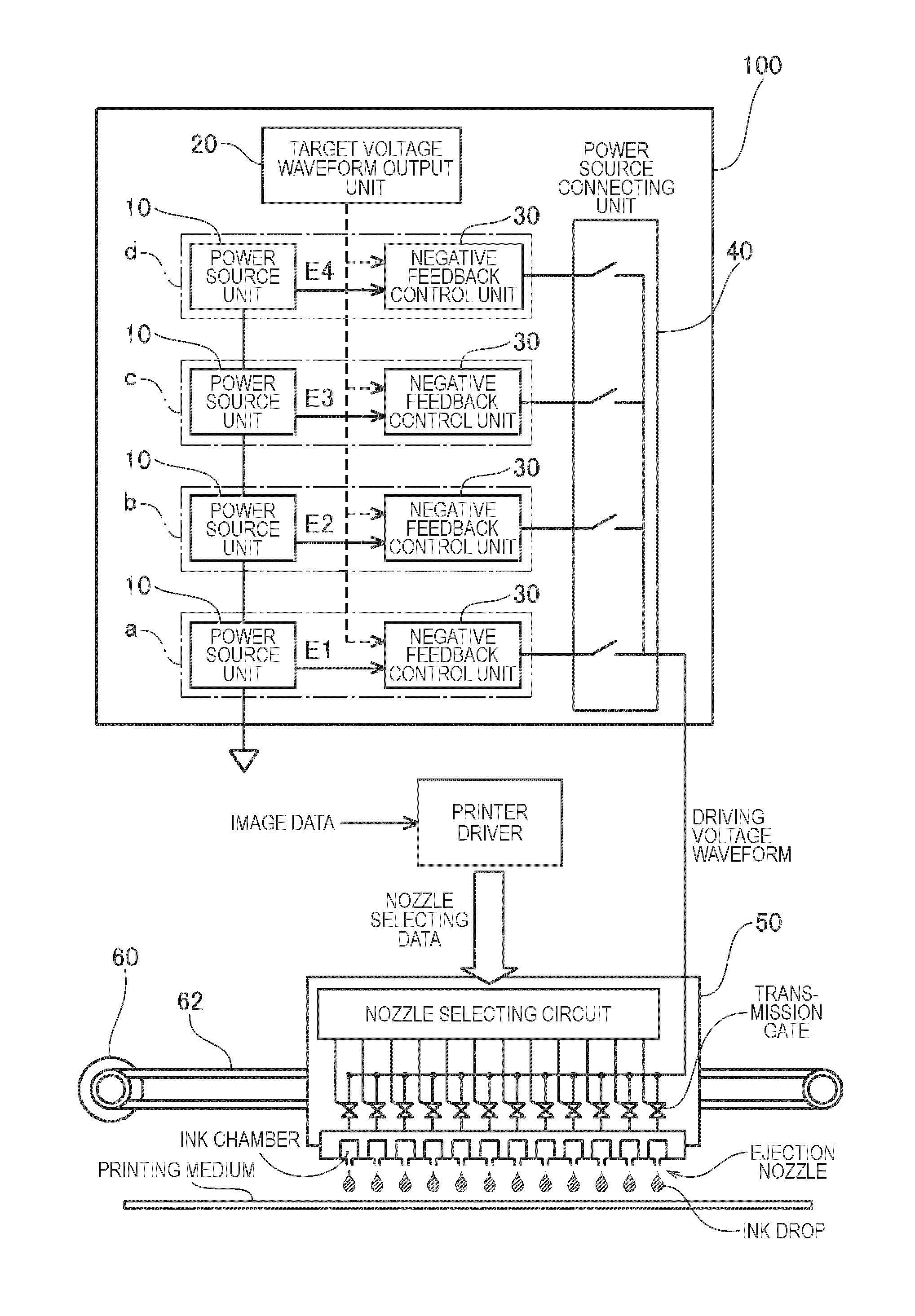
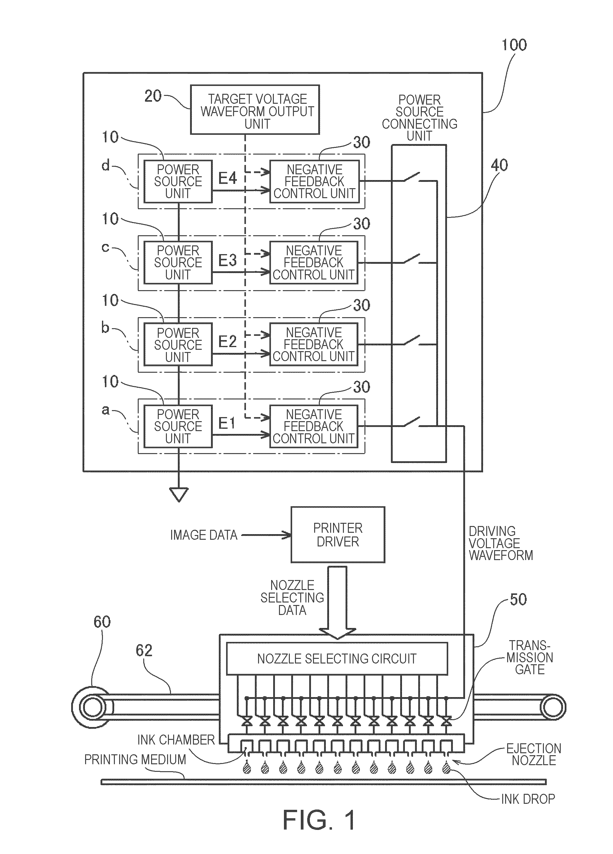
[0080]FIG. 3 is an explanatory drawing illustrating the configuration of the ejection head driving circuit according to a first embodiment. In the illustrated example, four power sources E1 to E4 are provided, and the electric powers generated by the respective power sources E1 to E4 are connected to the ejection head 50 via unipolar-type NMOS transistors Ntr1 to Ntr4. The first embodiment is based on the assumption of the case in which the ejection head 50 is a resistive load, and the ejection head driving circuit 100 in the first embodiment reduces the power consumption using only the effect achieved by the reduction of the operational potential difference and does not use the effect achieved by the power recovery from the ejection head 50. In such a case, any types of the power sources may be used as the power sources E1 to E4 such as...

second embodiment

C. Second Embodiment

Embodiment in which an Effect of an Operational Potential Difference Reduction and an Electric Power Recovery

C-1: Configuration of Ejection Head Driving Circuit

[0108]FIG. 8 is an explanatory drawing illustrating the configuration of the ejection head driving circuit 100 according to the second embodiment. In the ejection head driving circuit 100 according to the second embodiment, the four power sources E1 to E4 are provided in the same manner as the ejection head driving circuit 100 according to the first embodiment shown in FIG. 3, and generate the electric powers having the voltage values E1, E2, E3, and E4, respectively. Also, the electric powers from the respective power sources E1 to E4 are connected to the ejection head 50 via the unipolar type NMOS transistors Ntr1 to Ntr4. In the second embodiment, since the electric power stored in the ejection head 50 needs to be recovered and reused, power sources which can store at least part of the electric power su...

first modified embodiment

D-1. First Modified Embodiment

[0131]In the second embodiment described above, the power sources E1 to E4 which generate voltages higher than the voltage value applied to the ejection head 50 are connected to the ejection head 50 while the driving voltage is increasing, and the power sources E1 to E4 which generate voltages lower than the voltage value applied to the ejection head 50 are connected to the ejection head 50 while the driving voltage is reducing. Therefore, as shown in FIG. 10B, only one of the respective switches of SN1 to SN4 and SP0 to Sp3 are turned ON. In contrast, it is also possible to drive the ejection head 50 while connecting a power source unit which generates a higher voltage value and a power source unit which generates a lower voltage value than that applied to the ejection head 50 simultaneously.

[0132]FIGS. 11A to FIG. 11C are explanatory drawings showing a state of driving the ejection head 50 in the ejection head driving circuit 100 according to a first ...


PUM


Abstract

An ejection head driving circuit that supplies a driving voltage waveform to an ejection head has ejection nozzles that cause fluid to be ejected. A target voltage waveform output unit outputs a target voltage waveform to the ejection head. Power source units generate electric power at different voltage values. Negative feedback control units supply electric power from the respective power source units to the ejection head and perform a negative feedback control of the voltage values so that the voltage value to be applied to the ejection head matches the target voltage waveform. A power source connecting unit selects one of the power source units on the basis of the voltage value applied to the ejection head or the voltage value of the target voltage waveform, connects the selected power source unit to the ejection head, and disconnects the remaining power source units from the ejection head.

Description

[0001]This application claims priority to Japanese Patent Application No. 2008-275231 filed on Oct. 27, 2008, and the entire disclosure thereof is incorporated herein by reference.BACKGROUND[0002]1. Technical Field[0003]The present invention relates to a technique to discharge fluid from an ejection head having minute ejection nozzles by supplying a driving voltage waveform to the ejection head.[0004]2. Related Art[0005]So-called an ink-jet printer is capable of printing a high-quality image by discharging ink of an accurate amount to accurate positions from minute ejection nozzles, and is nowadays widely used. It is also considered to be possible to manufacture various minute components such as electrodes, sensors, or biochips by discharging various types of fluid instead of ink toward a substrate using this technique.[0006]In the technique as described above, a specific ejection head is employed so as to enable discharge of fluid such as ink by an accurate amount at accurate posit...

Claims


Application Information

Patent Timeline
Patent Type & Authority Applications(United States)
IPC IPC(8): B41J29/38
CPCB41J2/04541B41J2/04588B41J2/04581B41J2/04573
Inventor MIYAZAKI, SHINICHIYAMAZAKI, KATSUNORI
Owner SEIKO EPSON CORP
Why Eureka
Try Eureka