
Positioning wafer lenses on electronic imagers

Active Publication Date: 2010-04-29
JABIL CIRCIUT
View PDF8 Cites 230 Cited by
  • Summary
  • Abstract
  • Description
  • Claims
  • Application Information

AI Technical Summary

Benefits of technology

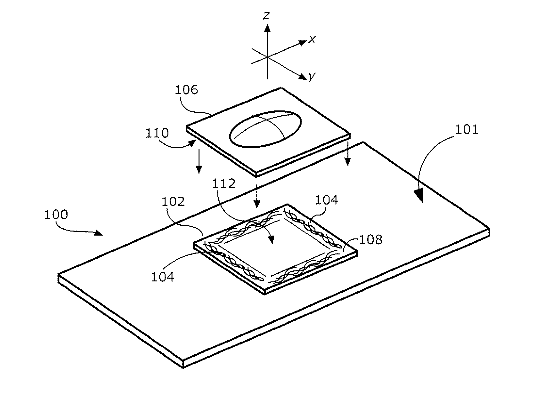
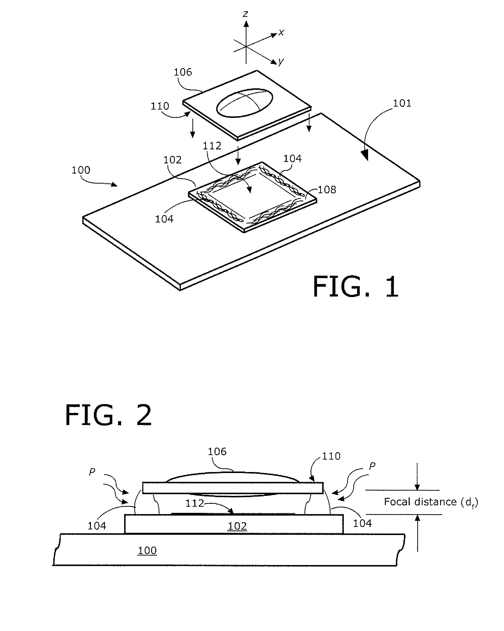
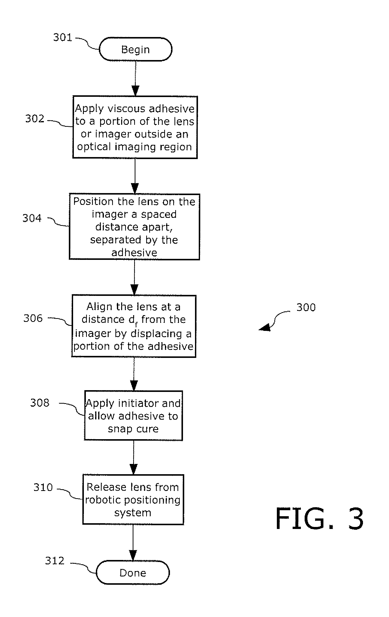
[0009]The variations in spacing between the lens and the electronic imager are accommodated by the viscous adhesive during the lens alignment process. The adhesive is able to move and remain attached to the lens and imager as their relative position is changed. After alignment is achieved the adhesive is snap cured using an initiator, such as an ultra-violet light source, thereby fixing the lens into the optimal focal position. The solution eliminates the need for a lens barrel and / or a fixed standoff to achieve the focal length—hence reducing overall product cost. The stack of adhesive is the exclusive support mechanism for the lens in the completed assembly. The adhesive also allows the alignment system to compensate for a wide range of tolerance issues within the lens, the imager and any additional cover glass.

Problems solved by technology

The thickness or height of the adhesive is tall or thick enough such that when the elements are assembled in this way, the lens is too far from the electronic imager in relation to the focal length of the lens.

Method used


Image

  • Positioning wafer lenses on electronic imagers
  • Positioning wafer lenses on electronic imagers
  • Positioning wafer lenses on electronic imagers

Examples


Embodiment Construction

[0016]The present invention is described with reference to the attached figures, wherein like reference numerals are used throughout the figures to designate similar or equivalent elements. The figures are not drawn to scale and they are provided merely to illustrate the instant invention. Several aspects of the invention are described below with reference to example applications for illustration. It should be understood that numerous specific details, relationships, and methods are set forth to provide a full understanding of the invention. One having ordinary skill in the relevant art, however, will readily recognize that the invention can be practiced without one or more of the specific details or with other methods. In other instances, well-known structures or operations are not shown in detail to avoid obscuring the invention. The present invention is not limited by the illustrated ordering of acts or events, as some acts may occur in different orders and / or concurrently with o...


PUM


Abstract

A low cost manufacturing method (300) and assembly (100) for positioning a lens (106) relative to an electronic imager (102). A viscous adhesive (104) is applied to the lens (106) or the electronic imager (102) outside of the optical path. The lens (106) is disposed on the electronic imager (102) exclusively with the adhesive (104) disposed between them.

Description

BACKGROUND OF THE INVENTION[0001]1. Field of the Invention[0002]The present invention relates to imaging systems and more particularly to positioning of wafer lenses on imager dies.[0003]2. Description of Related Art[0004]Electronic imagers are commonly used in photo-imaging applications. The imager is typically formed from charge-coupled-devices (CCD) or complementary metal oxide semiconductor (CMOS) devices. The imager contain many thousands of transistors which define pixels arranged in an array. The pixels are used to convert light into electrical signals that can then be stored and recalled by a processing device to produce an image.[0005]Imagers can be formed in various structures. For example, they can be formed as separate imager dies, as part of chip scale packaging (CSP), or as part of through-silicon via (TSV) modules. Regardless of the particular construction, however, a lens is generally required to focus an image upon the pixels of an imager die. The lens must be posit...

Claims


Application Information

Patent Timeline
IPC IPC(8): H04N5/225
CPCH01L27/14625H01L27/14685H04N17/002H04N5/2257H04N5/2254H04N23/57H04N23/55
Inventor BUTTERFIELD, ANDREWFABRE, SEBASTIENKUJANPAA, KARO
Owner JABIL CIRCIUT
Learn More