
Inner Pipe Fixation Device

a technology for fixing devices and inner pipes, which is applied in the direction of soldering auxilary devices, cable-laying vessels, pipe-laying vessels, etc., can solve the problem that the connection device does not allow any movement of the inner pipe, and achieve the effect of reducing the risk of human errors, high accuracy, and easy follow-up of the behavior of the inner pip

Inactive Publication Date: 2010-04-29
HEEREMA MARINE CONTRACTORS NEDERLAND
View PDF6 Cites 9 Cited by
  • Summary
  • Abstract
  • Description
  • Claims
  • Application Information

AI Technical Summary

Benefits of technology

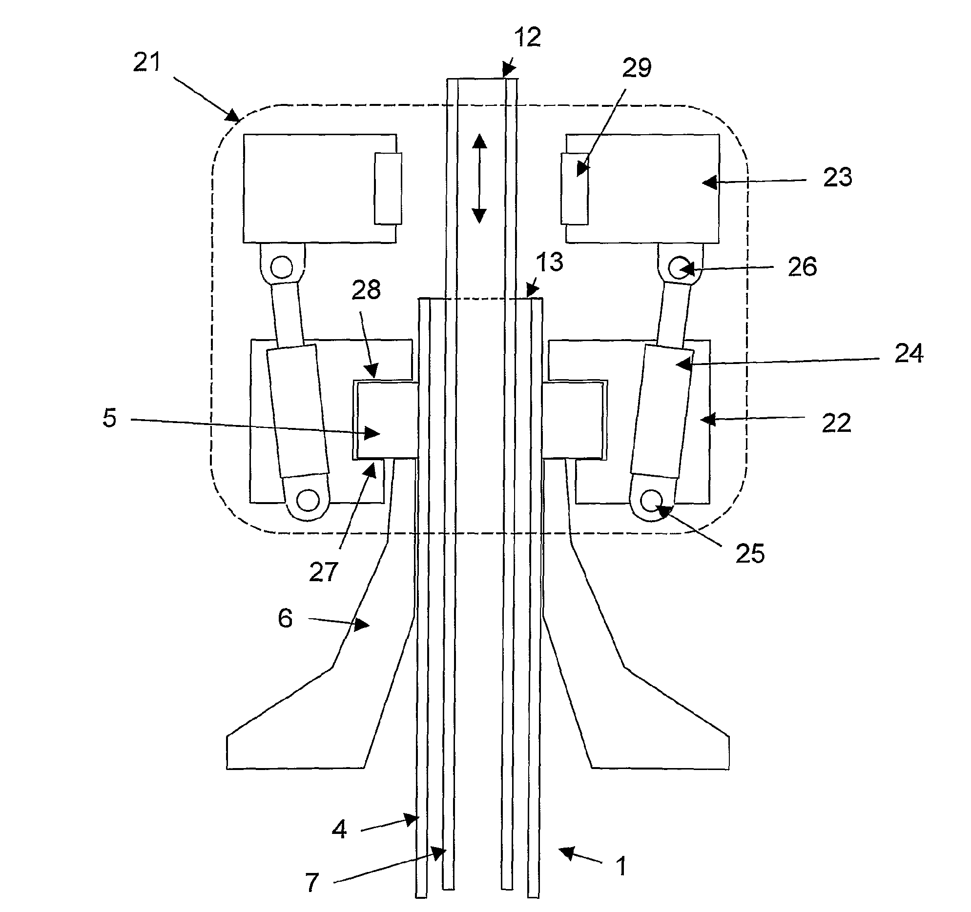
[0011]It is desirable to provide a fixation device for fixation of an inner pipe of a double-walled pipe with respect to a pipe laying structure and / or an outer pipe of said double-walled pipe, which fixation device allows relatively easy an quick fixation of said inner pipe in a certain position or position range in order to make proper welding of a new inner pipe section on the inner pipe of an existing pipeline, in particular in a J-lay tower, possible.
[0016]Since the transfer from the flexible state to the fixation state can be performed relatively quickly the position and / or the motion speed at which the inner pipe will be fixated can be predicted accurately and / or at a motion speed at which no huge forces will be induced in the fixation device or in the inner pipe.
[0020]The determination whether the inner pipe has reached the desired position for fixation may be done visually by an operator. However, it is preferred that a sensor device is provided which sensor device is configured to determine the position of said inner pipe with respect to said pipe laying structure an / or said outer pipe. With such sensor device the position of the inner pipe may be determined with high accuracy and the behavior of the inner pipe can be followed more easily. Furthermore, the risk on human errors is reduced.

Problems solved by technology

The connection device does not allow any movement of said inner pipe with respect to the pipe laying structure or outer pipe to which the connection device is connected.

Method used


Image

  • Inner Pipe Fixation Device
  • Inner Pipe Fixation Device
  • Inner Pipe Fixation Device

Examples


Embodiment Construction

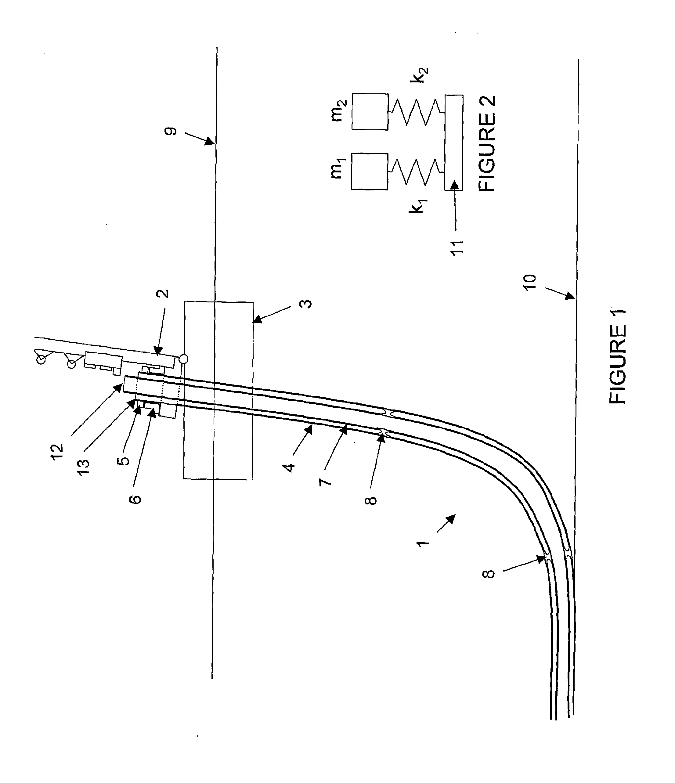
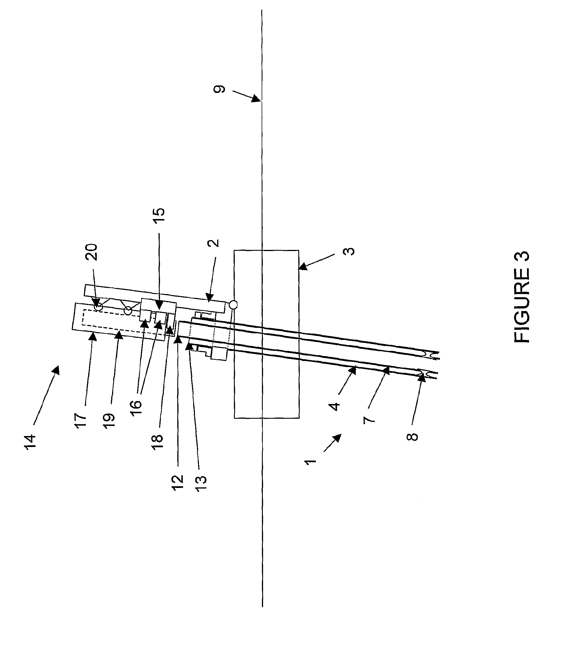
[0046]FIG. 1 shows a pipe laying vessel 3 comprising a J-lay tower for laying double walled pipelines 1 to a sea bed 10. Such double-walled pipeline generally comprises an outer pipe 4 and an inner pipe 7.

[0047]When laying a double walled (pipe-in-pipe) pipeline 1 to a seabed 10 by means of a J-Lay Tower 2 mounted on a pipelaying vessel 3, the outer pipe 4 is hung off from a collar 5 welded to the outer pipe 4, the collar 5 resting on a hang-off table 6 which is axially rigidly supported by the J-Lay Tower 2. Alternatively, the outer pipe may be held by a tensioner device rigidly connected to the J-Lay Tower 2 or by any other suitable device known in the art.

[0048]The inner pipe 7 is in axial direction supported by bulkheads 8 connecting the inner pipe 7 to the outer pipe 4 at substantially regular intervals. As an alternative, any other suitable connection between the outer pipe 4 and the inner pipe 7 may be used.

[0049]Due to motions of the pipelaying vessel 3 on the sea surface 9,...


PUM


Abstract

The present invention relates to a fixation device for fixation of a position of an inner pipe of a double-walled pipe with respect to a pipe laying structure and / or an outer pipe of said double-walled pipe, said fixation device comprising: an inner pipe gripping device (23) configured to grip said inner pipe, and a connection device (24,25,2S) configured to connect said inner pipe gripping device with said pipe laying structure and / or said outer pipe, said connection device having a flexible state in which, during use, the inner pipe gripping device is movable with respect to said pipe laying structure and / or said outer pipe, and a fixation state in which, during use, the inner pipe gripping device is fixated with respect to the pipe-laying structure and / or said outer pipe.

Description

CROSS-REFERENCE TO RELATED APPLICATIONS[0001]This application is the National Stage of International Application No. PCT / NL2006 / 000501, filed Oct. 4, 2006, the contents of which is incorporated by reference herein.FIELD OF THE INVENTION[0002]The present invention relates to a fixation device configured to fixate a position of an inner pipe of a double-walled pipe with respect to an outer pipe of said double-walled pipe. Furthermore, the invention relates to a fixation device to fixate a position of an inner pipe of a double walled pipe with respect to a pipe-laying structure during the welding of a new inner pipe section to an inner pipe of an existing pipeline.BACKGROUND[0003]In the offshore industry there is a need for underwater pipelines. These underwater pipelines may be provided by joining pipe sections together in a substantially vertical position to form a pipeline which is lowered from a vessel to an underwater bottom, for instance the bottom of the sea. In such pipe laying...

Claims


Application Information

Patent Timeline
IPC IPC(8): F16L1/12B63B35/03
CPCB23K37/0533F16L1/23F16L1/207
Inventor VAN EGMOND, JAN
Owner HEEREMA MARINE CONTRACTORS NEDERLAND
Learn More