Apparatus and method for rotating a fire, a flame, a smoke plume, or for circulating heat

a technology for rotating devices and fires, applied in lighting and heating apparatus, combustion process, dental prosthetics, etc., can solve the problems of no regular movement and no functionality for rotating flames, and achieve the effect of optimizing the resulting air circulation and further adjusting the devi

Active Publication Date: 2010-04-29
MOTTELI JOHN BRENT
View PDF8 Cites 25 Cited by
  • Summary
  • Abstract
  • Description
  • Claims
  • Application Information

AI Technical Summary

Benefits of technology

[0010]The gas inlet openings can be formed as gas inflow oriented channel sections or can be formed as nozzles. Thus the air current of an inlet gas through a gas inlet opening is forced along a flow direction following the direct line of communication, whether straight or curved, between the location of the respective gas inlet opening and the enlarged area of the chamber in which the heat source is located. Alternatively or additionally, concerning the gas inlet openings, the means of orientation of gas inflow may be located on the inside of the chamber wall. In a specific embodiment, these channel sections are formed as a straight channel extending from the outside to the inside wall of the chamber through the chamber wall, as a hole or bore through the chamber wall. Instead of a bore, the channels can be formed as any desired form, for example, rectangular cross sections. The channels or nozzles can be straight or curved. If they are curved, they are curved to begin to move the air passing therethrough in a circular motion about the heat source before actual entry of the directed gas into the chamber. The alignment of the channel sections is preferably such that the axis of the channel and the tangent of the wall in the area of the channel form an acute angle. This angle should lie in the range between approximately 5° to 45°. In this way, deceleration of the inlet gas by “wall friction” with the chamber inner walls can be minimized, and secondly, a sufficiently large torque can be exerted on the gas in the chamber, so that a sufficiently strong rotational movement of the chamber gases can be attained around the heat source.
[0024]One can also provide further adjustability of the device by allowing the direction and / or the cross section of the inlet port forming the channels or nozzle to be adjustable. When using jets or channels which taper inwardly toward the outlet end on the chamber, the swirling turbulent gas flowing in the chamber can be taken into account to optimize the resulting air circulation.

Problems solved by technology

With such known devices, a flame or a plume can be moved, but apart from an irregular motion caused by the gas flow turbulence generated by a flame or smoke plume, or the draft of air in a room or in an exterior environment, there are no regular movements, and especially no functionality which rotates a flame or a plume of smoke.

Method used


Image

  • Apparatus and method for rotating a fire, a flame, a smoke plume, or for circulating heat
  • Apparatus and method for rotating a fire, a flame, a smoke plume, or for circulating heat
  • Apparatus and method for rotating a fire, a flame, a smoke plume, or for circulating heat

Examples


embodiment 60

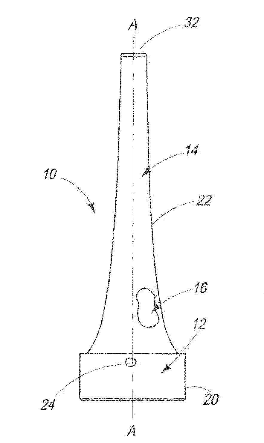
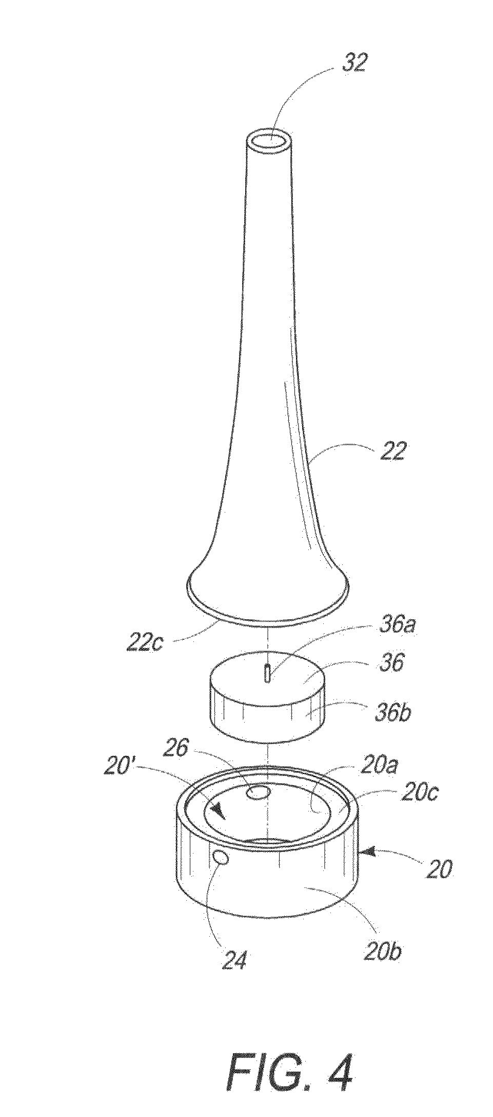
[0054]FIG. 6 is a cross sectional view of a second alternate embodiment 60 of the invention, made in a single piece, preferably by glass injection molding. An advantage of this embodiment 60 is its simplicity in that it is composed essentially of a single chimney portion 62 in which holes 64 (corresponding to holes 24, 26 and 30) are formed. The lower portion 66 is open and so the device can be placed over a burning candle 68. In addition, using this embodiment, one can adjust the central position of the candle very easily, to ensure that the flame remains at the center of the chamber 16′, simply by displacing the device, until the desired flame motion is obtained.

embodiment 70

[0055]FIG. 7 is a perspective view of a third alternate embodiment 70 of the invention, used to distribute smoke and / or fragrance from a plurality of satallitic incense burners 72. These incense burners72 include a base portion 74 and a transparent cover portion 76 allowing an air inlet opening 77. The base portion 74 receives and contains the burning incense 78. The cover portion 76 directs the smoke and / or aroma of the incense through tube portions 80 which enter into the gas inlet openings 24, 26 and 30, thereby feeding the smoke or aroma into the chamber 22 where it is mixed by the revolving gases and then disbursed in the air through the gas outlet opening 32. Note that the height of the base portion 20 is increased in this embodiment to allow the tube portions 80 to enter at the level of the flame 28 (i.e., to allow for the height of the incense burners 72). Further, where additional oxygen is needed in such an arrangement, additional gas inlet opening / channels 81 can be provi...

embodiment 120

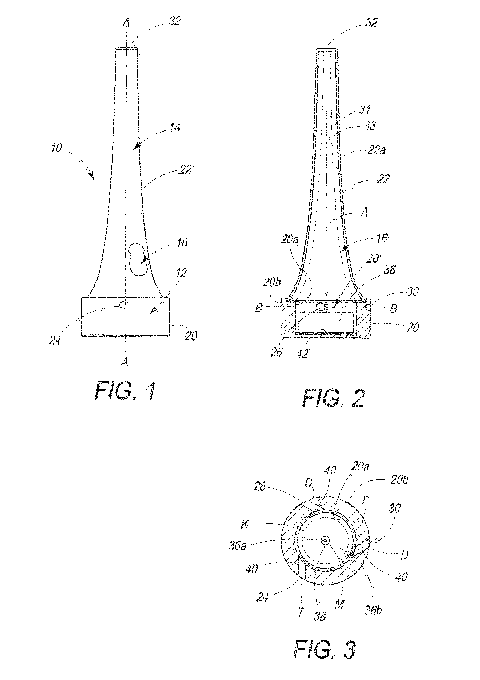
[0057]FIG. 9 is a top, sectional view of a fifth alternate embodiment 120 in which the invention includes gas inlets 24′, 26′, and 30′ whose direction is adjustable via a housing 122 in which they are formed that pivots on an axis 124. In this embodiment, the angle α can be varied by, for example, moving the housing 122 via the handle 126. Alternatively, as mentioned above, the angle and position, as well as speed of fans 130 can be computer controlled, in order to optimize the heat convection and transfer in the system. Note that seals sealing between the housing 122 and the base portion 20″ or around the door 92′ which seal against unwanted air drafts are not shown, the design of which believed to be well within the capabilities of someone of ordinary skill in the art.

[0058]In an advantage, the invention provides a source of light and heat, or a visual stimulus which is desirable and unique.

[0059]In another advantage, the invention provides a “light spiel” which requires no batter...


PUM


Abstract

The invention relates to a device (10) and a method for rotating a flame and / or a plume of smoke, arranged with a heat source (36) in a chamber (16) with at least one gas inlet opening (24, 26, 30) and a gas outlet opening (32). The gas inlet opening (24, 26, 30) and the heat source (36) are located in a lower area (12, 20′) of the chamber (16). The gas outlet opening (32) is located in an upper region (14) of the chamber (1.6). In this way, an ascending gas flow may be generated in the chamber (16). At least one gas inlet channel or nozzle (24, 26, 30, 40) is adapted to direct inflowing gas therethrough into the lower area (12, 20′) of the chamber (16) approximately along an inner wall of the chamber about an at least approximately circular path following along the inner wall in the same rotational sense around the heat source and then is drawn upwardly by a draw of the upwardly flowing heated gases though the gas outlet opening (32). A flame or smoke plume inside the chamber (16) can thereby be placed into a rotary motion.

Description

CROSS REFERENCE TO RELATED APPLICATIONS[0001]This application claims the benefit of Swiss Patent Application No. CH 1564 / 08 filed Oct. 2, 2008, and U.S. Provisional Application No. 61 / 104,276, filed Oct. 10, 2008, the contents of which are incorporated by reference herein.COPYRIGHT & LEGAL NOTICE[0002]A portion of the disclosure of this patent document contains material which is subject to copyright protection. The copyright owner has no objection to the facsimile reproduction by anyone of the patent document or the patent disclosure as it appears in the Patent and trademark Office patent file or records, but otherwise reserves all copyright rights whatsoever. Further, no references to third party patents or articles made herein is to be construed as an admission that the present invention is not entitled to antedate such material by virtue of prior invention.BACKGROUND OF THE INVENTION[0003]The invention relates to a device for rotating a fire, flame, a plume of smoke or for circul...

Claims


Application Information

Patent Timeline
Patent Type & Authority Applications(United States)
IPC IPC(8): F23C99/00
CPCF23D3/16F21V35/00F24B1/19F23D3/18
Inventor RYSER, ANDREAS
Owner MOTTELI JOHN BRENT
Why Eureka
Try Eureka