Apparatus and method for ultrasonic testing

a technology of ultrasonic testing and apparatus, applied in the direction of mechanical roughness/irregularity measurement, using reradiation, instruments, etc., can solve the problems of reducing signal intensity, accuracy and sensitivity, and difficulty in obtaining a sufficient s/n ratio of receive signals

Inactive Publication Date: 2010-04-29
HITACHI LTD
View PDF6 Cites 76 Cited by
  • Summary
  • Abstract
  • Description
  • Claims
  • Application Information

AI Technical Summary

Benefits of technology

[0060]The above-mentioned method enables three-dimensional measurement of the distance between echoes in a simple way in sizing a defect such as a crack.

Problems solved by technology

However, the synthetic aperture method described in the first background art has a problem that it is difficult to obtain a receive signal having a sufficient S / N ratio.
Since this method uses a single ultrasonic transducer having a small sensor aperture, applying it to a case with a long propagation distance of ultrasonic wave disperses or attenuates the ultrasonic wave signal resulting in a decrease in signal intensity.
Although the second background art provides favorable accuracy and sensitivity in imaging directly under a two-dimensional array ultrasonic sensor, there has been a problem that both accuracy and sensitivity fall in imaging at a position not directly under the ultrasonic sensor.

Method used


Image

  • Apparatus and method for ultrasonic testing
  • Apparatus and method for ultrasonic testing
  • Apparatus and method for ultrasonic testing

Examples


first embodiment

[0108]Configuration and operation of an ultrasonic testing apparatus according to the present invention will be described below with reference to FIGS. 1 to 14.

[0109]First of all, the configuration of the ultrasonic testing apparatus according to the present embodiment will be described below with reference to FIG. 1.

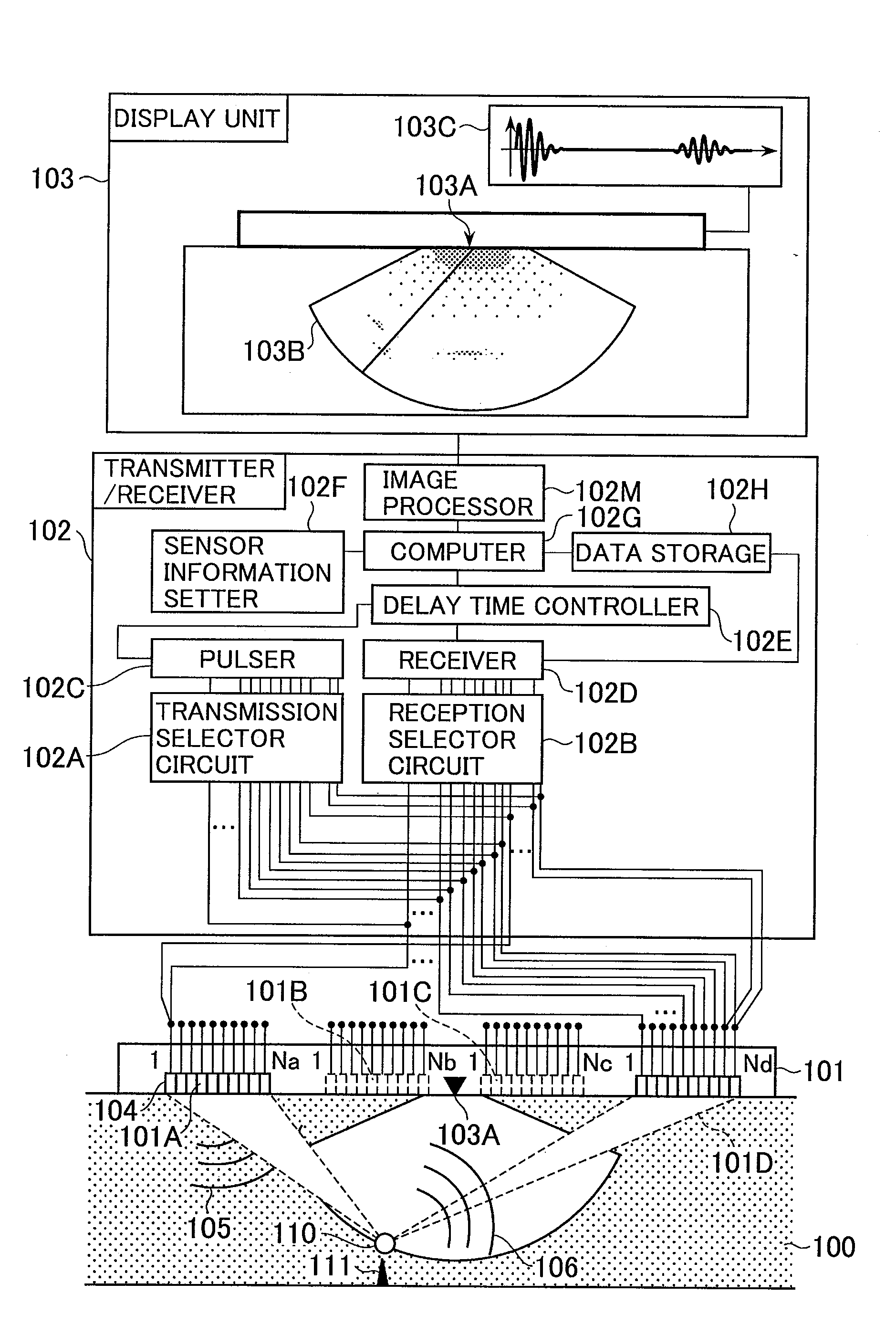
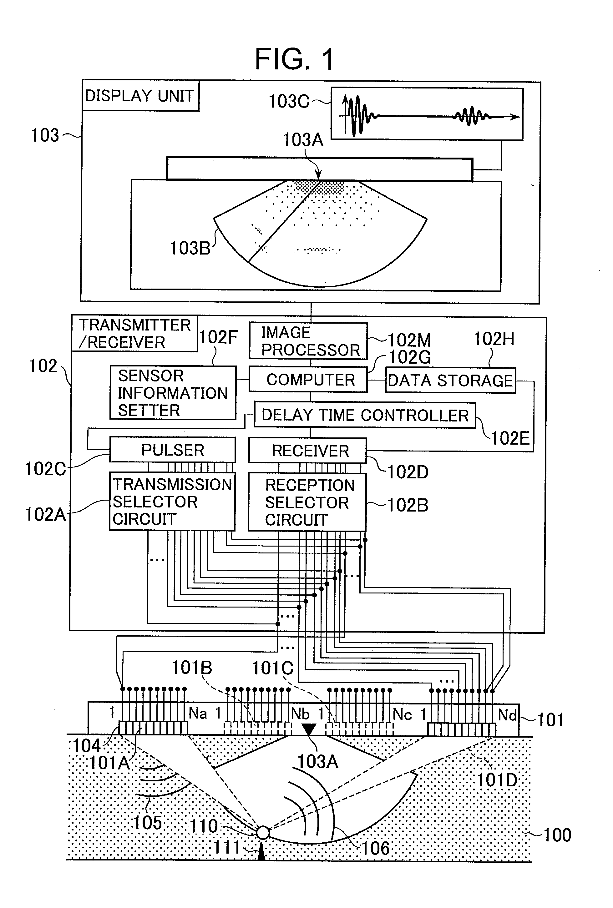
[0110]FIG. 1 is a block diagram illustrating a configuration of the ultrasonic testing apparatus according to the first embodiment of the present invention.

[0111]The ultrasonic testing apparatus according to the present embodiment includes an ultrasonic array transducer 101 which transmits ultrasonic waves to an object under test 100, a transmitter / receiver 102, and a display unit 103 which displays testing images. The present embodiment tests a reflection source 111 such as a defect and a crack in the inside or on the surface of the object under test 100 by imaging.

[0112]The ultrasonic array transducer 101 is basically composed of a plurality of one- or two-dimensional...

second embodiment

[0171]Configuration and operation of an ultrasonic testing apparatus according to the present invention will be described below with reference to FIGS. 15 to 17. The configuration of the ultrasonic testing apparatus according to the present embodiment is the same as that shown in FIG. 1.

[0172]First of all, a sensor center position setup in the ultrasonic testing apparatus according to the present embodiment will be described below with reference to FIGS. 15 and 16.

[0173]FIGS. 15 and 16 illustrate a sensor center position setup in the ultrasonic testing apparatus according to the second embodiment of the present invention.

[0174]With the present embodiment, although processing flow is the same as that of the first embodiment, the sensor center position setup (step S1102 of the flow chart in FIG. 11) is extended.

[0175]Although all the piezoelectric elements composing an ultrasonic array transducer are grouped into a plurality of element clusters in the first embodiment, FIG. 15 shows a...

third embodiment

[0183]Configuration and operation of an ultrasonic testing apparatus according to the present invention will be described below with reference to FIGS. 18 to 21. The configuration of the ultrasonic testing apparatus according to the present embodiment is the same as that shown in FIG. 1.

[0184]FIGS. 18 and 20 illustrate element cluster combination setups in the ultrasonic testing apparatus according to the third embodiment of the present invention. FIGS. 19 and 21 illustrate display screens in the ultrasonic testing apparatus according to the third embodiment of the present invention.

[0185]With the present embodiment, the array transducer 101 is composed of four element clusters.

[0186]FIGS. 18 and 20 illustrate exemplary element cluster combination setups used for transmission and reception. FIG. 18 illustrates a case where a second receive signal Ψ is derived from all the 16 first receive signals Φ obtained by the four element clusters. These combinations of element clusters are the...


PUM

PropertyMeasurementUnit
frequencyaaaaaaaaaa
wavelengthaaaaaaaaaa
sonic velocityaaaaaaaaaa

Abstract

An apparatus and a method for ultrasonic testing obtains high-resolution and high-S/N ratio testing results by driving a number of piezoelectric elements using fewer pulsers and receivers in comparison with the number of elements composing an array transducer. A sensor information setter sets a plurality of piezoelectric element groups used for transmission and a plurality of piezoelectric element groups used for reception among the plurality of piezoelectric elements composing an ultrasonic array transducer. A computer transmits an ultrasonic wave from the element cluster set for transmission, and stores an ultrasonic wave received by the element cluster set for reception. The procedure is repeated including different element cluster sets for transmission and reception to obtain first receive signals. The first receive signals are summed to obtain a second receive signal; and the second receive signal is displayed with reference to the sensor center position on a display unit.

Description

BACKGROUND OF THE INVENTION[0001]1. Field of the Invention[0002]The present invention relates to an apparatus and a method for ultrasonic testing which is one of non-destructive testing methods. More particularly, the present invention is related to an apparatus and a method for ultrasonic testing by using an array ultrasonic sensor.[0003]2. Description of the Related Art[0004]Conventional ultrasonic testing methods targeting various kinds of structural materials utilize an ultrasonic sensor composed of a single element for transmission and reception of an ultrasonic wave. The ultrasonic sensor receives an ultrasonic signal reflected by a defect or the like inside an object under test to detect a defect based on the propagation time of the ultrasonic signal and the position of the ultrasonic sensor.[0005]Specifically, conventional methods comprises the steps of: appropriately selecting an angle and vibration mode (longitudinal wave, transversal wave, etc.) of an ultrasonic wave to b...

Claims


Application Information

Patent Timeline
Patent Type & Authority Applications(United States)
IPC IPC(8): G01N29/04
CPCG01N29/04G01S15/8925G01N29/07G01S15/8927G01S15/8997G01N29/2468G01N2291/106G01S15/8993G01S15/8918G01N29/262
Inventor BABA, ATSUSHIKITAZAWA, SOKONO, NAOYUKI
Owner HITACHI LTD
Why Eureka
Try Eureka