Multi-part piston for an internal combustion engine

a multi-part, internal combustion engine technology, applied in the direction of engines, mechanical equipment, machines/engines, etc., can solve the problems of difficult structure production, change in the microstructure of materials in the ring land region, etc., to achieve good cooling effect of cooling oil, effective lubrication of the piston pin, and not impaired stability of the lower piston parts

Active Publication Date: 2010-05-06
MAHLE INT GMBH
View PDF7 Cites 25 Cited by
  • Summary
  • Abstract
  • Description
  • Claims
  • Application Information

AI Technical Summary

Benefits of technology

[0006]It is therefore an object of the invention to provide a piston of the stated type, in such a manner that a good cooling effect of the cooling oil in the in...

Problems solved by technology

However, such a structure is difficult to produce.
In the case of a forged lower piston part, in particular, there is the ...

Method used


Image

  • Multi-part piston for an internal combustion engine
  • Multi-part piston for an internal combustion engine
  • Multi-part piston for an internal combustion engine

Examples


Embodiment Construction

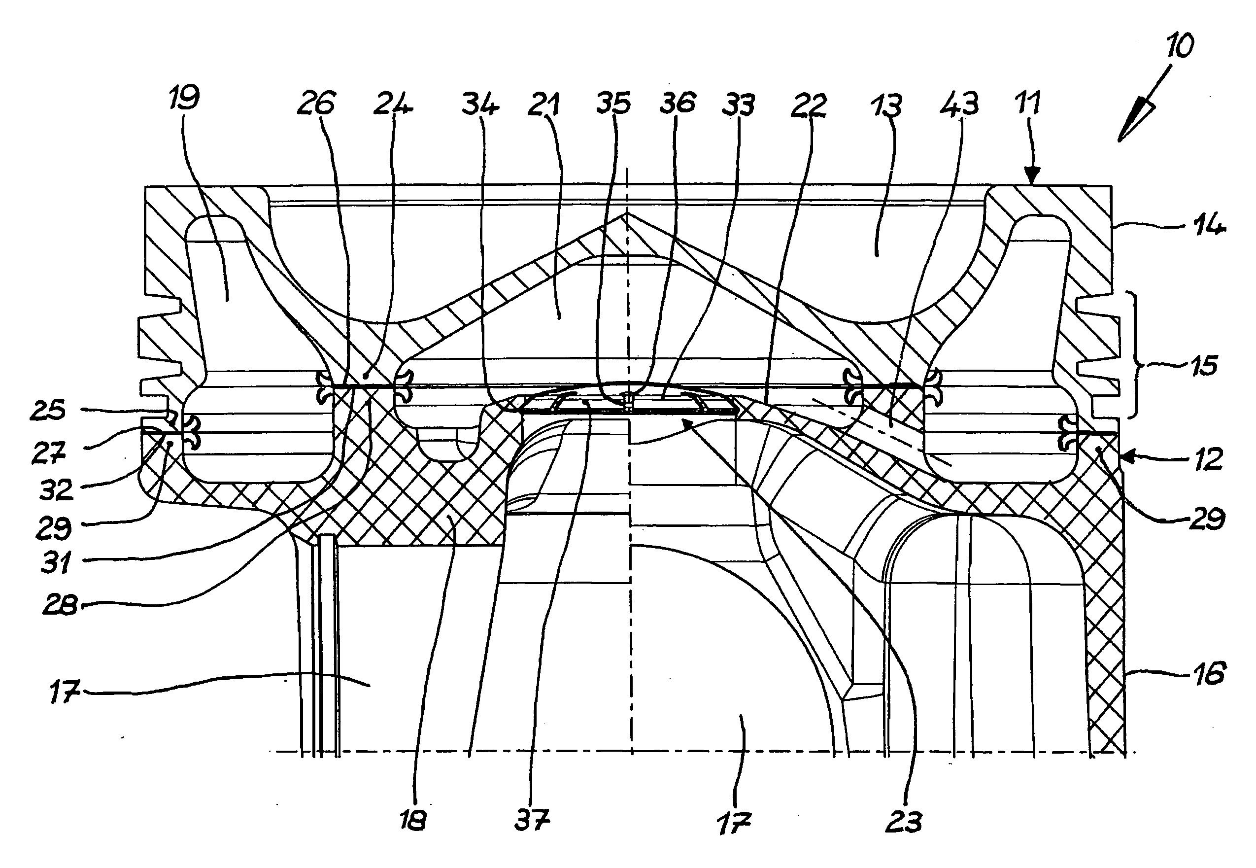
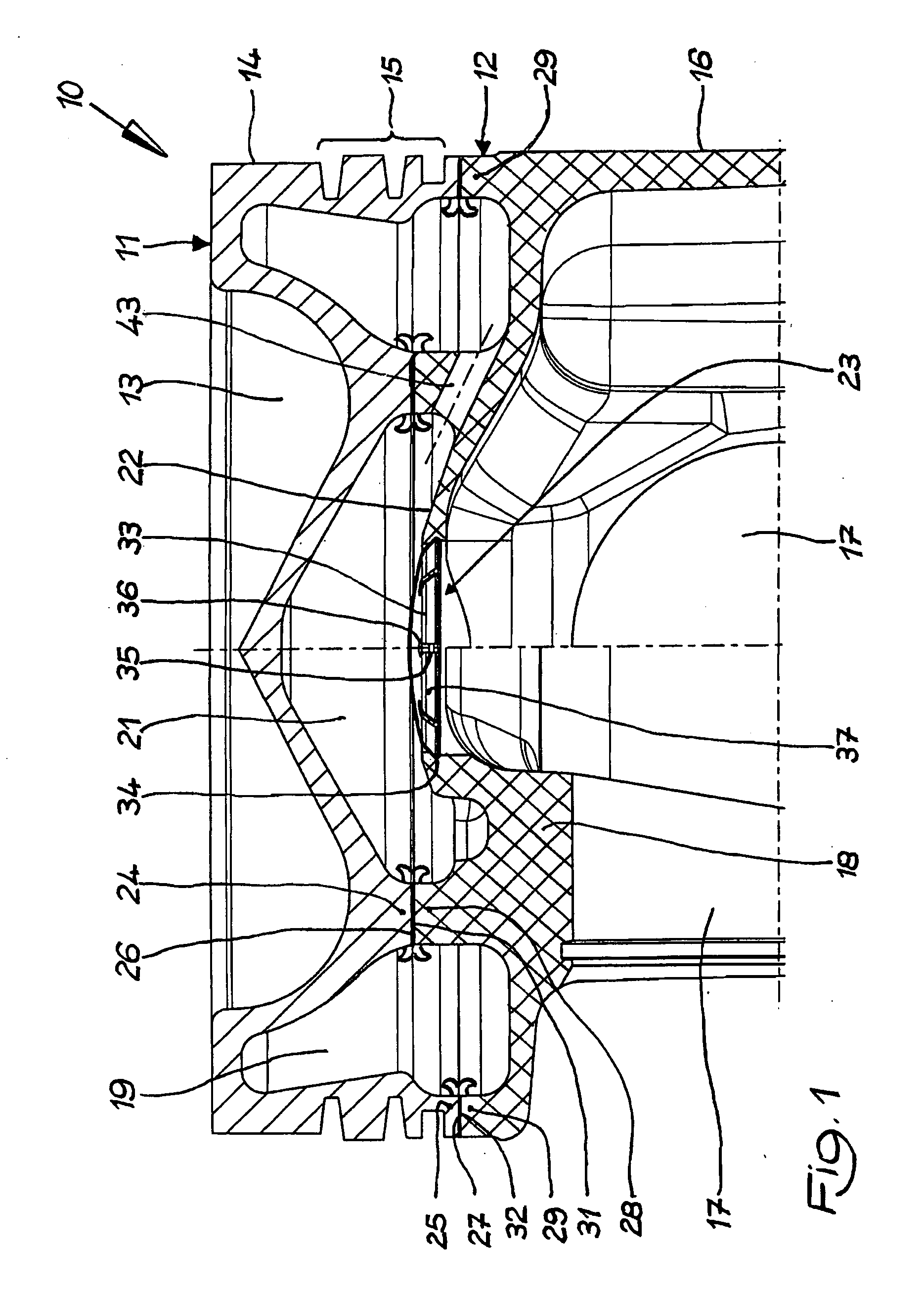
[0019]Referring now in detail to the drawings, FIG. 1 shows a first exemplary embodiment of a piston 10 according to the invention, which is forged from a steel material in the exemplary embodiment. Piston 10 according to the invention is composed of an upper piston part 11 and a lower piston part 12. Upper piston part 11 has a combustion bowl 13, a circumferential top land 14, and a circumferential ring belt 15. Lower piston part 12 has a piston skirt 16, pin bores 17 for accommodating a piston pin, and pin bosses 18. Upper piston part 11 and the lower piston part 12 form a circumferential outer cooling channel 19 and a central inner cooling chamber 21. Cooling chamber bottom 22 of cooling chamber 21 is provided with a relatively large opening 23.

[0020]Upper piston part 11 has an inner support element 24 and an outer support element 25. Inner support element 24 is disposed on the underside of upper piston part 11, circumferentially, in ring shape, and has a joining surface 26. Inne...


PUM


Abstract

A multi-part piston for an internal combustion engine has an upper piston part and a lower piston part. The upper piston part and the lower piston part each have an inner and an outer support element, which elements delimit an outer circumferential cooling channel and an inner cooling chamber, whose cooling chamber bottom has an opening. The opening is closed off with a separate closure element, which has at least one cooling oil opening

Description

CROSS REFERENCE TO RELATED APPLICATIONS[0001]Applicants claim priority under 35 U.S.C. §119 of German Application No. 10 2008 055 908.3 filed Nov. 5, 2008.BACKGROUND OF THE INVENTION[0002]1. Field of the Invention[0003]The present invention relates to a multi-part piston for an internal combustion engine, having an upper piston part and a lower piston part. The upper piston part and the lower piston part each have an inner and an outer support element, which elements delimit an outer circumferential cooling channel and an inner cooling chamber. The cooling chamber bottom has an opening.[0004]2. The Prior Art[0005]A piston of this type is disclosed in European Patent No. EP 1 222 364 B1. The opening in the cooling chamber bottom allows cooling oil to flow away out of the inner cooling chamber in the direction of the piston crown, in order to lubricate the piston pin. In order to achieve this goal, the opening in the cooling chamber bottom cannot be too large, because then, the coolin...

Claims


Application Information

Patent Timeline
IPC IPC(8): F01P1/04F02F3/00F01B31/08
CPCF02F3/22F02F2003/0061
Inventor SCHARP, RAINERMUELLER, REINEREDEL, HELMUTGRAF, BERNDKOHNLE, STEFANHELD, DIETERSEIFRIED, MATTHIAS
Owner MAHLE INT GMBH
Why Eureka
Try Eureka