Multi-part piston for an internal combustion engine

Inactive Publication Date: 2010-05-06
MAHLE INT GMBH
View PDF13 Cites 12 Cited by
  • Summary
  • Abstract
  • Description
  • Claims
  • Application Information

AI Technical Summary

Benefits of technology

[0006]It is therefore an object of the invention to provide a piston of the stated type, in such a manner that good cooling of the cooling oil in the interior o

Problems solved by technology

However, such a structure is difficult to produce.
In the case of a forged lower piston part, in particular, there is the additional problem that the microstru

Method used


Image

  • Multi-part piston for an internal combustion engine
  • Multi-part piston for an internal combustion engine
  • Multi-part piston for an internal combustion engine

Examples


first embodiment

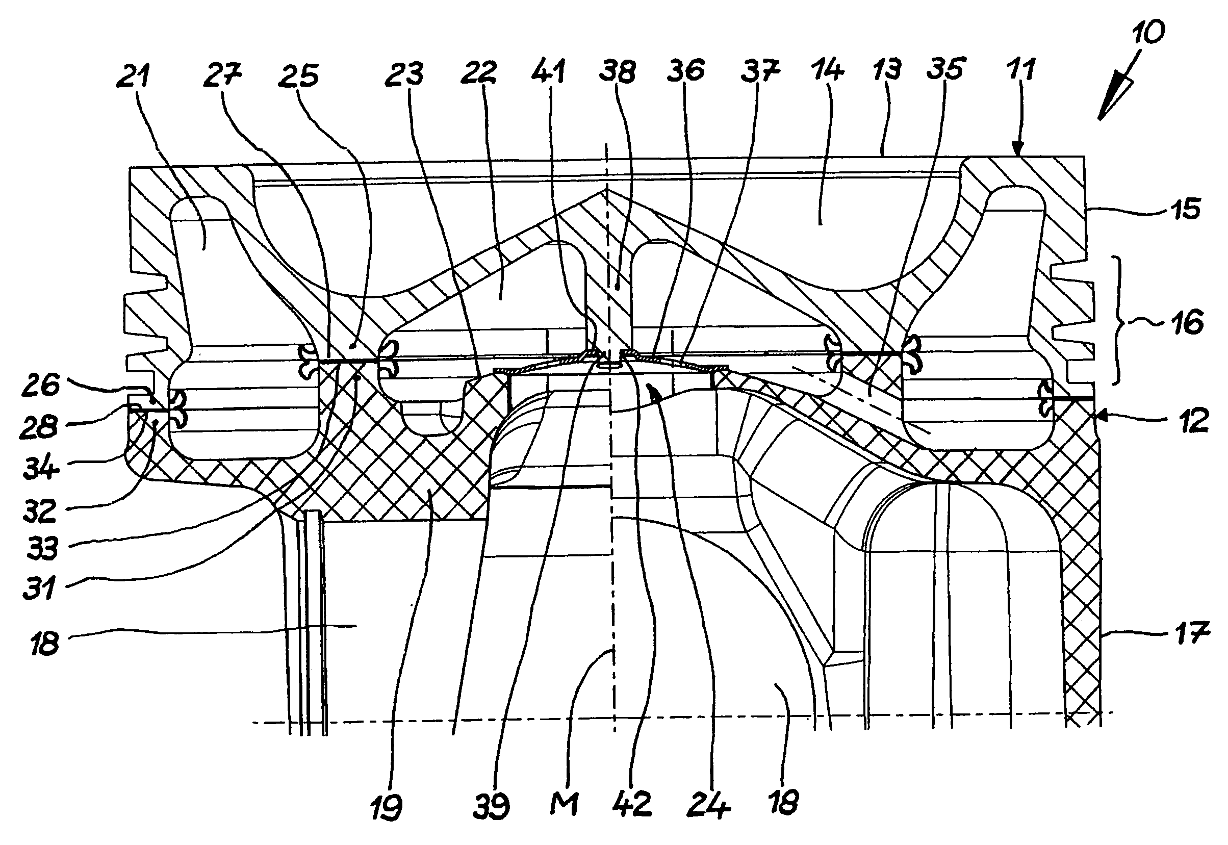
[0025]Referring now in detail to the drawings and, in particular, FIG. 1 shows a piston 10 according to the invention, which is forged from a steel material in this embodiment. Piston 10 according to the invention is composed of an upper piston part 11 and a lower piston part 12. Upper piston part 11 has a piston crown 13 having a combustion bowl 14, a circumferential top land 15, and a circumferential ring belt 16. Lower piston part 12 has a piston skirt 17, pin bores 18 for accommodating a piston pin, and pin bosses 19. Upper piston part 11 and the lower piston part 12 form a circumferential outer cooling channel 21 and a central inner cooling chamber 22. Cooling chamber bottom 23 of cooling chamber 22 is provided with a relatively large opening 24.

[0026]Upper piston part 11 has an inner support element 25 and an outer support element 26. Inner support element 25 is disposed on the underside of upper piston part 11, circumferentially, in ring shape, and has a joining surface 27. I...

second embodiment

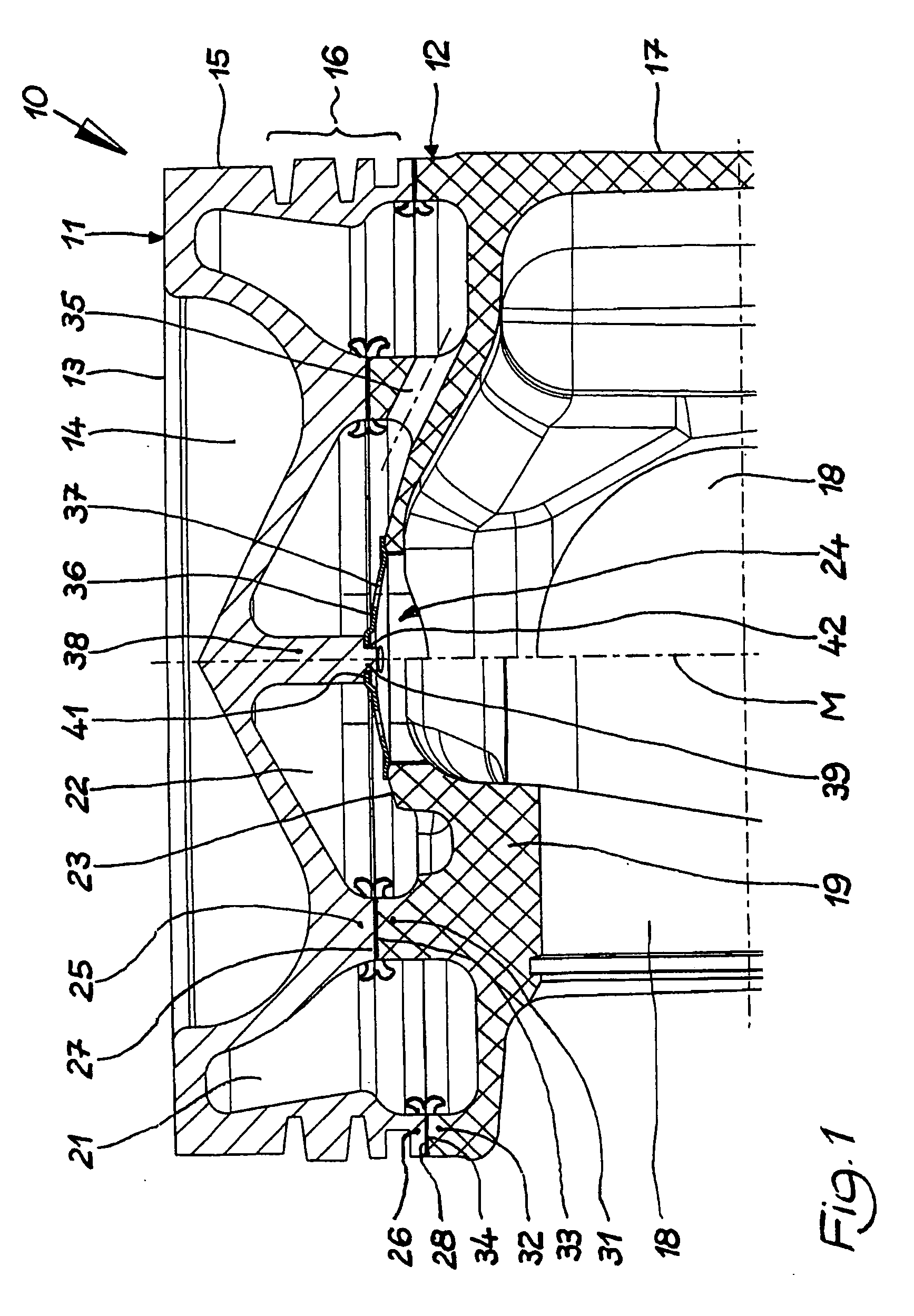
[0031]FIG. 2 shows a piston 110 according to the invention. Piston 110 has essentially the same construction as piston 10 according to FIG. 1, so that the same structures are provided with the same reference symbols, and with regard to these reference symbols, reference is made to the description of FIG. 1.

[0032]A significant difference as compared with piston 10 according to FIG. 1 consists in the fact that in piston 110, the holding element 138 is present as a separate component. In the embodiment shown, holding element 138 is provided with a conical depression 143 at its end that faces piston crown 13. The underside of piston crown 13 has a corresponding conical elevation 144. Holding element 138 has a projection 139 at its end that faces closure element 36, which projection is surrounded by a circumferential contact shoulder 141. Projection 139 passes through a central recess 42 provided in closure element 36, whereby contact shoulder 141 lies on the top of closure element 36. T...

third embodiment

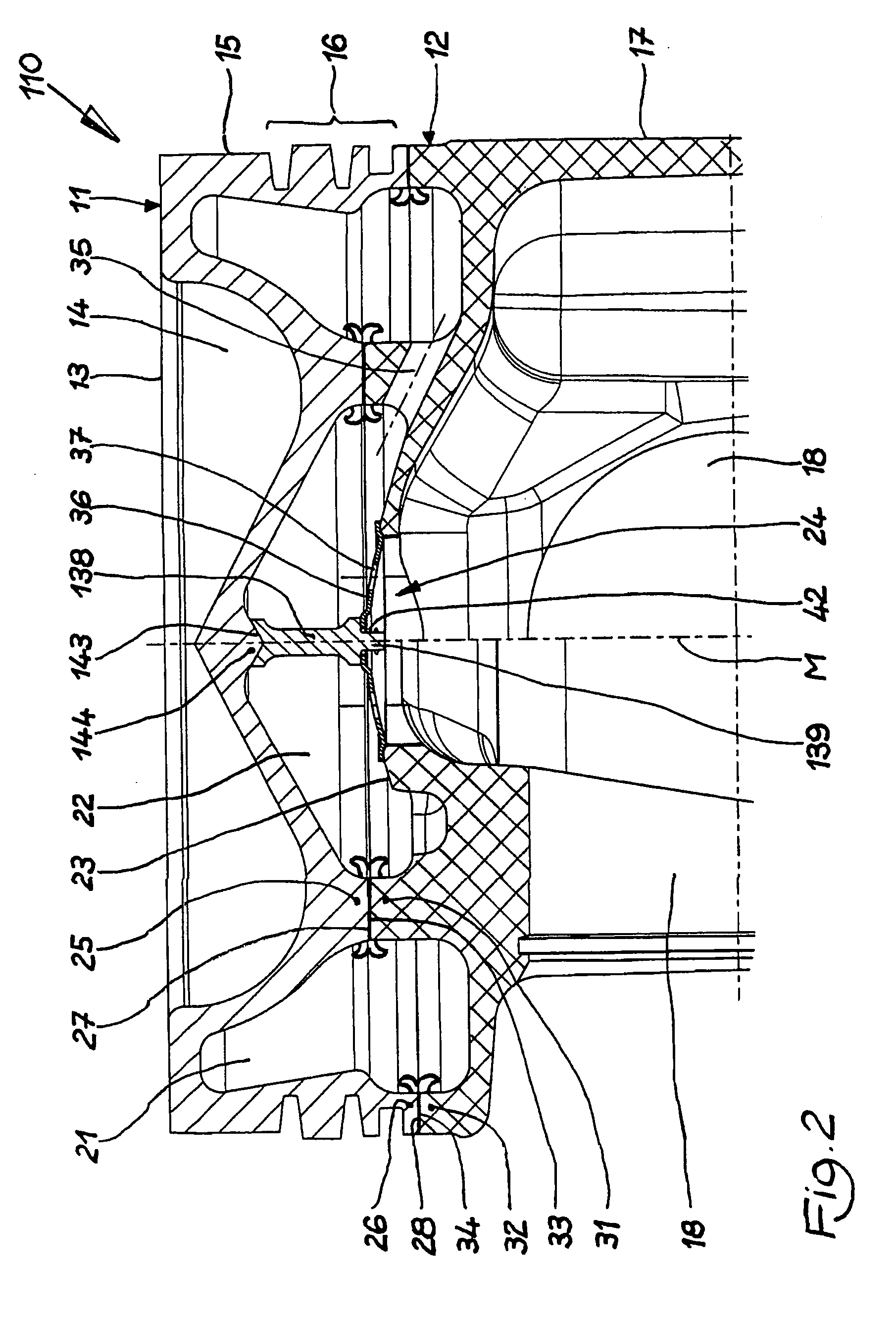
[0033]FIG. 3 shows a piston 210 according to the invention. Piston 210 has essentially the same construction as piston 10 according to FIG. 1, so that the same structures are provided with the same reference symbols, and with regard to these reference symbols, reference is made to the description of FIG. 1.

[0034]In the case of piston 210, as well, holding element 238 is configured as a separate component. In contrast to piston 110 according to FIG. 2, holding element 238 has a journal 245 at its end that faces piston crown 13. The underside of piston crown 13 is provided with a corresponding dead-end hole 246, in which journal 245 is accommodated. Holding element 238 has a circumferential groove 247 at its end that faces closure element 36, in which groove closure element 36 is held by snapping it in. The length of holding element 238 is dimensioned in such a way, in the embodiment shown, that closure element 36 supports itself on cooling chamber bottom 23 under resilient bias. Clos...


PUM


Abstract

A multi-part piston for an internal combustion engine has an upper piston part with a piston crown, and a lower piston part, each of the piston parts having an inner and an outer support element that delimit an outer circumferential cooling channel and an inner cooling chamber. The cooling chamber bottom has an opening. A holding element is disposed in the inner cooling chamber and extends from the underside of the piston crown vertically toward the opening. The holding element carries a closure element that closes the opening and has at least one cooling oil opening.

Description

CROSS REFERENCE TO RELATED APPLICATIONS[0001]Applicant claims priority under 35 U.S.C. §119 of German Application No. 10 2008 055 909.1 filed Nov. 5, 2008.BACKGROUND OF THE INVENTION[0002]1. Field of the Invention[0003]The invention relates to a multi-part piston for an internal combustion engine, having an upper piston part that has a piston crown, and a lower piston part. Each of the piston parts has an inner and an outer support element, which elements delimit an outer circumferential cooling channel and an inner cooling chamber, whose cooling chamber bottom has an opening.[0004]2. The Prior Art[0005]A piston of this type is disclosed in European Patent No. EP 1 222 364 B1. The opening in the cooling chamber bottom allows cooling oil to flow away out of the inner cooling chamber in the direction of the piston crown, in order to achieve a cooling effect as a consequence of the oil passage from the outer circumferential cooling channel to the inner cooling chamber, and to lubricate...

Claims


Application Information

Patent Timeline
IPC IPC(8): F02F3/00F01B31/00
CPCF02F3/003F02F3/22
Inventor SCHARP, RAINER
Owner MAHLE INT GMBH
Why Eureka
Try Eureka