
Methods, systems and apparatus for paced breathing

Active Publication Date: 2010-05-06
RESMED LTD
View PDF4 Cites 70 Cited by
  • Summary
  • Abstract
  • Description
  • Claims
  • Application Information

AI Technical Summary

Benefits of technology

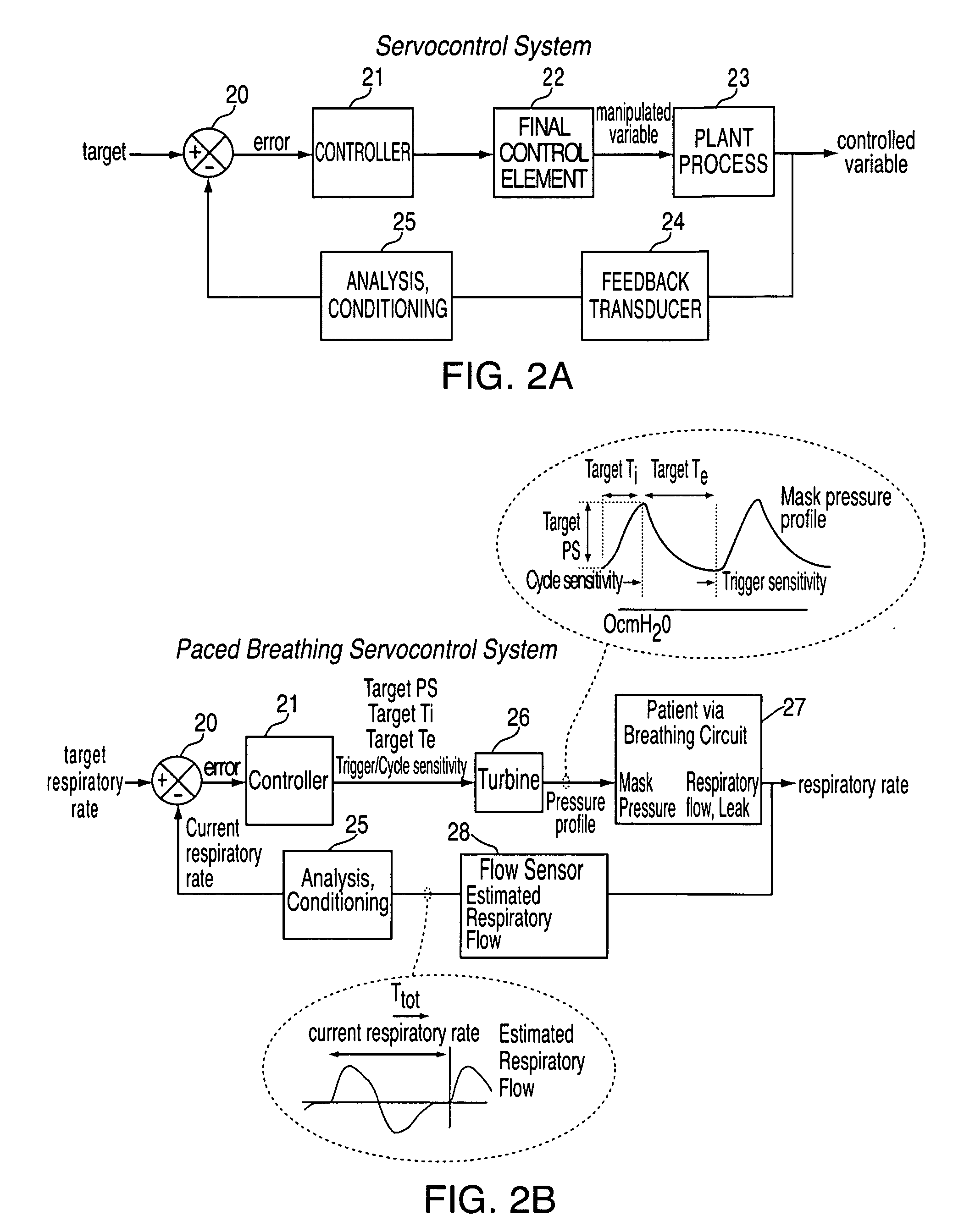
[0013]In certain embodiments, the variable pressure waveform cycles from an inhalation phase to an exhalation phase when the patient airflow decreases to a cycle threshold, the cycle threshold being a function of flow versus time within a breath and generally increasing with time. Different interim breathing rate targets have different cycle threshold functions, and the cycle threshold functions allow easier cycling as the interim breathing rate targets decrease. Similarly, the variable pressure waveform triggers from an exhalation phase to an inhalation phase when the patient airflow increases to a trigger threshold, the trigger threshold being a function of flow versus time within a breath and generally decreasing with time. Different interim breathing rate targets have different trigger threshold functions, and the trigger threshold functions allow easier triggering as the interim breathing rate targets decrease.
[0036]In certain embodiments, the different interim breathing rate targets have different trigger threshold functions, and the trigger threshold functions allow easier triggering as the interim breathing rate targets decrease.

Problems solved by technology

Hypertension and cardiac failure are both diseases that cannot always be controlled with current medications.

Method used


Image

  • Methods, systems and apparatus for paced breathing
  • Methods, systems and apparatus for paced breathing
  • Methods, systems and apparatus for paced breathing

Examples


Embodiment Construction

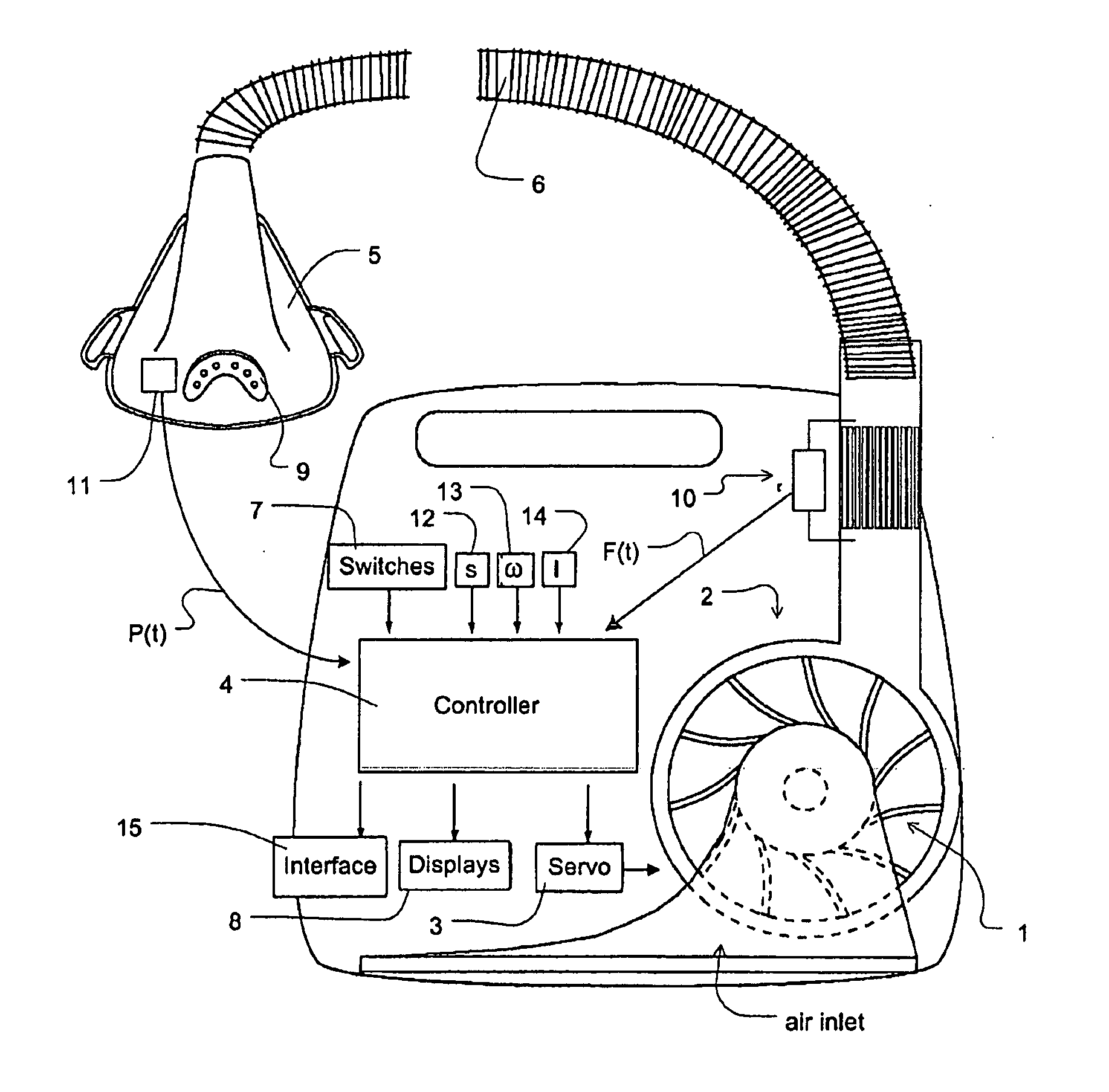
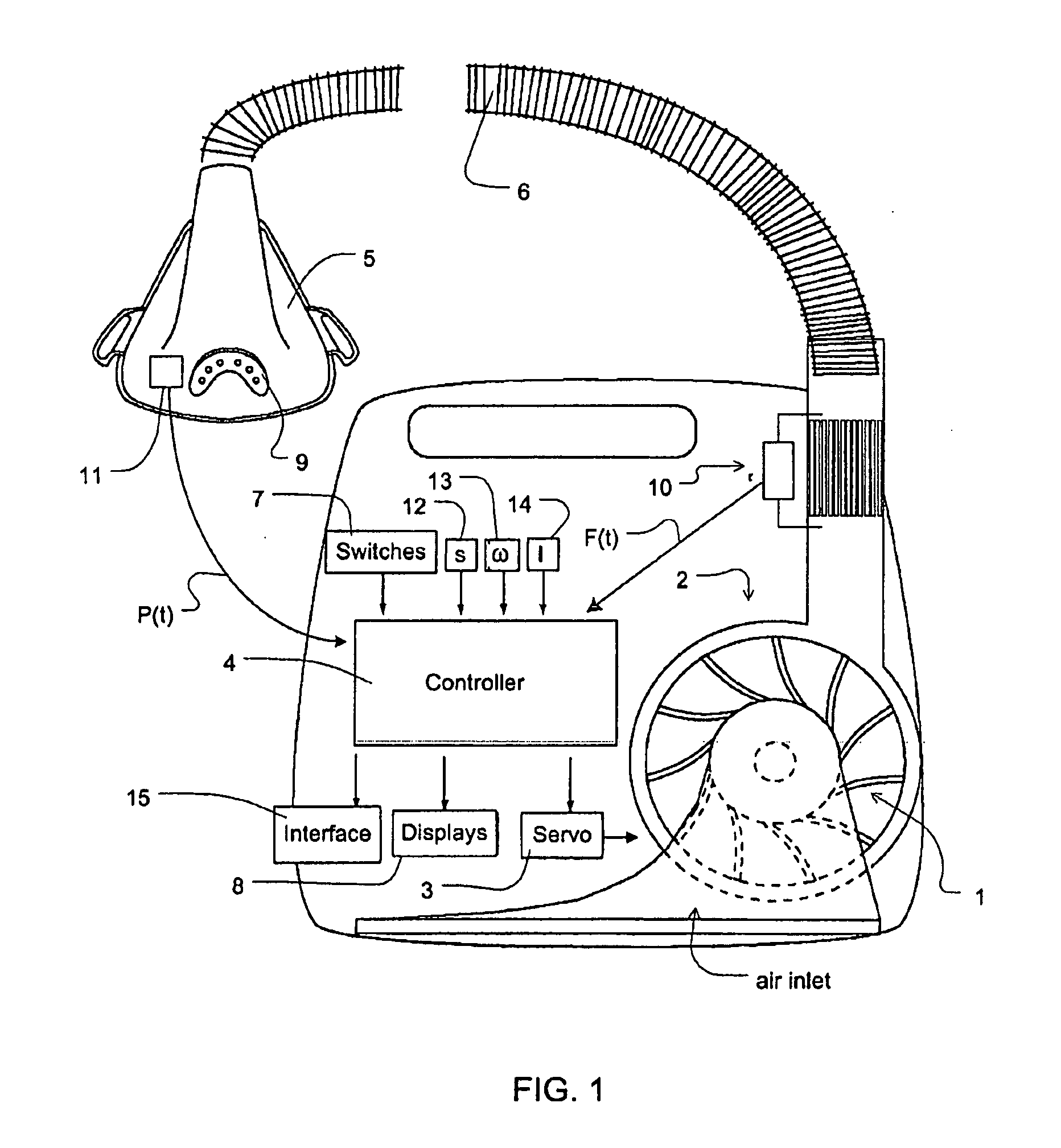
[0053]FIG. 1 shows, by way of example, apparatus suitable for performing certain disclosed embodiments. The apparatus includes an impeller 1 connected to an electric motor 2 under the control of a servo-controller 3 which is in turn under the control of a controller 4. In one form the controller 4 is a micro-processor based controller. The impeller 1 and motor 2 form a blower. Air from the blower passes along a flexible conduit 6 to a patient interface such as a nasal mask 5 with a vent 9. While a nasal mask is illustrated, certain disclosed embodiments may be used in conjunction with a nose-and-mouth mask, full face mask, endotracheal tube or other devices that perform the desired function. A number of switches 7 are connected to the controller. A number of sensors are also connected to the controller, namely, sensors for flow 10, pressure 11, snore 12, motor speed 13 and motor current 14. A set of displays 8 connected to the controller 4 display information from the controller.

[00...


PUM


Abstract

Methods, systems and / or apparatus for slowing a patient's breathing by using positive pressure therapy. In certain embodiments, a current interim breathing rate target is set, and periodically the magnitude of a variable pressure waveform that is scaled to the current interim breathing rate target is increased if the patient's breathing rate is greater than the interim breathing rate target in order to lengthen the patient's breath duration. The magnitude of the pressure increase may be a function of the difference between the interim breathing rate target and the patient's breathing rate. The interim breathing rate target may be periodically reduced in response to the patient's breathing rate slowing down toward the current interim breathing rate target. The variable pressure waveform cycles from an inhalation phase to an exhalation phase when the patient airflow decreases to a cycle threshold, the cycle threshold being a function of flow versus time within a breath and generally increasing with time. Different interim breathing rate targets have different cycle threshold functions, and the cycle threshold functions allow easier cycling as the interim breathing rate targets decrease. Similarly, the variable pressure waveform triggers from an exhalation phase to an inhalation phase when the patient airflow increases to a trigger threshold, the trigger threshold being a function of flow versus time within a breath and generally decreasing with time. Different interim breathing rate targets have different trigger threshold functions, and the trigger threshold functions allow easier triggering as the interim breathing rate targets decrease.

Description

CROSS REFERENCE TO RELATED APPLICATIONS[0001]This application is a continuation-in-part of U.S. application Ser. No. 12 / 422,411, filed Apr. 13, 2009, which claims the benefit of U.S. Provisional Application No. 61 / 045,161 filed on Apr. 15, 2008. Both related applications, in their entirety, are each incorporated herein by reference.FIELD OF THE INVENTION[0002]The disclosure relates to methods, systems and apparatus for paced breathing.BACKGROUND OF THE INVENTION[0003]Hypertension and cardiac failure are both diseases that cannot always be controlled with current medications. With hypertension, any decrease in blood pressure (particularly pulse pressure) is beneficial. Hypertensive and cardiac failure patients possess heightened sympathetic tone (higher basal activity) and chemoreflex (hypoxic, relating to deficiencies of oxygen) response (a reflex initiated by the stimulation of chemoreceptors, which are specialized cells for detecting chemical substances and relaying that informati...

Claims


Application Information

Patent Timeline
IPC IPC(8): A61M16/00
CPCA61M2016/0036A61M16/026A61M2230/06A61M2230/205A61M2230/42A61M2205/502A61M16/0468A61M16/202A61M16/0672A61M16/204A61M16/0069A61M16/0003A61M2016/0018A61M2230/005
Inventor MARTIN, DION CHARLES CHEWEBASSIN, DAVID JOHN
Owner RESMED LTD
Learn More