Trench MOSFET with Trench Termination and manufacture thereof

Inactive Publication Date: 2009-03-05
FORCE MOS TECH CO LTD
View PDF9 Cites 94 Cited by
  • Summary
  • Abstract
  • Description
  • Claims
  • Application Information

AI Technical Summary

Benefits of technology

[0011]The present invention has some advantages. One is feasible for high cell density with pitch smaller than 2.4 μm while the P body is formed after trench formation and no Boron segregation issue which is feasible for higher cell density (cell pitch is less than 2.4 μm) to reduce On-re

Problems solved by technology

Another is that no N+ near edge of active area and termination area to improve device ruggedness

Method used


Image

  • Trench MOSFET with Trench Termination and manufacture thereof
  • Trench MOSFET with Trench Termination and manufacture thereof
  • Trench MOSFET with Trench Termination and manufacture thereof

Examples


Example

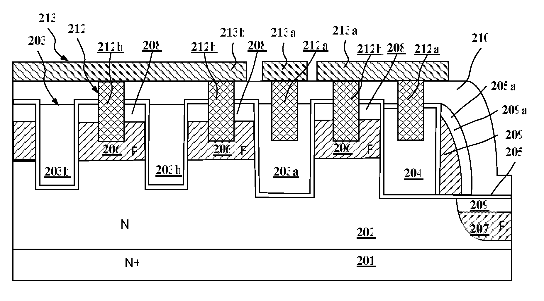
[0024]Referring to FIG. 2E showed a first embodiment again, the trench MOSFET with a trench termination of the present invention has a MOSFET structure comprises the drain region 201, the N-type doping epi layer region 202, the gate trenches 203, the margin terminating gate trench 204, the gate oxide layer 205, the channel regions 206, the margin terminating channel region 207, the source regions 208, the margin terminating source region 209, the insulating layer 210, the contact plugs 212, and the metal layer 213. The metal layer 213 comprises the first metal layer region 213a and the second metal layer region 213b which are formed on the top of the MOSFET structure, and the first metal layer region 213b and the second metal layer region 213a are formed as the source metal, and the gate and field plate metal of the MOSFET, respectively. The gate trenches 203 comprises the first gate trench 203a and the second gate trench 203b which are covered the gate oxide layer 205 and are defin...

Example

[0026]Referring to FIG. 3 showed a second embodiment, the P-doped regions of the trench MOSFET with a trench termination of the present invention can be alternatively formed by a deposition process so that a margin terminating sidewall channel region 207a is formed at a side of the margin terminating gate trench 204. Besides, a margin terminating sidewall source region 209a is also formed on the margin terminating sidewall channel region 207a during the source region process.

Example

[0027]Referring to FIG. 4 showed a third embodiment, the trench MOSFET with a trench termination of the present invention is similar to the first embodiment of the present invention. The second metal layer region 213b is divided into two parts which are the gate runner and the field plate metal of the MOSFET respectively.


PUM


Abstract

A trench MOSFET (Metal-Oxide-Semiconductor Field Effect Transistor) with a trench termination, including a substrate including a drain region which is strongly doped and a doping epi layer region, which is weekly doped the same type as the drain region, on the drain region; a plurality of source and body regions formed in the epi layer; a metal layer including a plurality of metal layer regions which are connected to respective source and body, and gate regions forming metal connections of the MOSFET; a plurality of metal contact plugs connected to respective metal layer regions; a plurality of gate trenches filled with polysilicon to form a plurality of trenched gates on top of epi layer; an insulating layer deposited on the epi layer formed underneath the metal layer with a plurality of metal contact holes therein for contacting respective source and body regions; a margin terminating gate trench which is around the gate trenches; and a margin terminating active region which is formed underneath the margin terminating gate trench.

Description


Claims


Application Information

Patent Timeline
IPC IPC(8): H01L47/00H01L21/336
CPCH01L29/0623H01L29/0661H01L29/407H01L29/66734H01L29/7811H01L2924/0002H01L29/7813H01L2924/00
Inventor HSHIEH, FWU-IUAN
Owner FORCE MOS TECH CO LTD
Why Eureka
Try Eureka