
Laterally diffused field effect transistor in soi configuration

Inactive Publication Date: 2018-12-20
GLOBALFOUNDRIES INC
View PDF14 Cites 2 Cited by
  • Summary
  • Abstract
  • Description
  • Claims
  • Application Information

AI Technical Summary

Benefits of technology

This patent describes a new way to design a transistor that can operate at high voltages while still reducing the chances of voltage drop and increasing conductivity. The design uses a fully depleted region that allows for a linear drop in voltage along its length, which also increases the speed of charge carriers. This new design can work well with existing small signal CMOS techniques and is also ideal for RF applications like power amplifiers. Overall, this new design helps improve the performance of transistors in high-voltage circuits and reduces the on-resistance.

Problems solved by technology

Although reduction of the critical dimensions is basically driven by a demand for ever-increasing transistor performance at low power consumption, it appears that these demands may frequently result in certain compromises that have to be made, since the reduction of critical dimensions to achieve high integration density and, thus, relatively low cost, is often associated with significant influences on transistor performance.
For example, upon steadily reducing the critical dimensions of sophisticated CMOS transistor elements, extremely high integration density may be achieved, for instance, by implementing several hundred millions of individual transistor elements into a single integrated circuit chip, thereby forming highly complex circuitry or even entire systems on a single chip.
Some of these adverse effects of the continuous reduction of the gate length of sophisticated field effect transistors are associated with the capacitive coupling between the conductive channel forming below the gate electrode structure, the parasitic capacitance of the remaining transistor body with respect to the gate electrode structure, thereby increasing static and dynamic leakage currents into and through a very thin gate dielectric material, and the like.
For example, capacitive coupling of the gate electrode structure to the channel region has required a continuous reduction of the physical thickness of the gate dielectric material, which, on the other hand, may significantly contribute to increased leakage currents into and through the thin gate dielectric material.
Due to the substantially intrinsic or lowly-doped state of the semiconductor material, appropriate mechanisms for adjusting the threshold voltage of respective transistors have been developed, since conventional threshold voltage adjusting mechanisms based on highly doped polysilicon are no longer effective.
Consequently, in view of many advantages offered by the SOI technique, highly complex integrated circuits have been designed so that small signal capabilities of modern integrated circuits are significantly enhanced, while, at the same time, the reduced overall dimensions contribute to superior speed of critical signal paths, also resulting in reduced power consumption.
Although transistor elements operating on the basis of increased supply voltages and higher drive currents may be formed on the basis of specific semiconductor compounds, such as gallium arsenide and the like, it turns out that such approaches may be associated with a significant increase in overall manufacturing costs and may, therefore, represent approaches less than desirable for many technical applications.
Although very promising approaches have been undertaken, it appears, however, that presently available LDMOS transistors may still contribute to increased on-resistance and / or reduced breakdown voltage and / or may lack compatibility with sophisticated CMOS techniques, thereby rendering any such approaches less than desirable for implementation in sophisticated SOI architectures as described above.

Method used


Image

  • Laterally diffused field effect transistor in soi configuration
  • Laterally diffused field effect transistor in soi configuration
  • Laterally diffused field effect transistor in soi configuration

Examples


Embodiment Construction

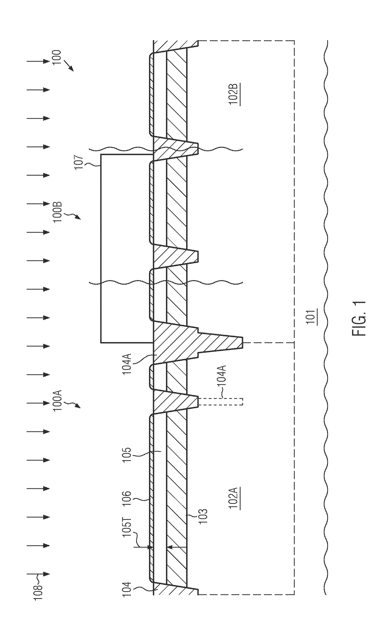
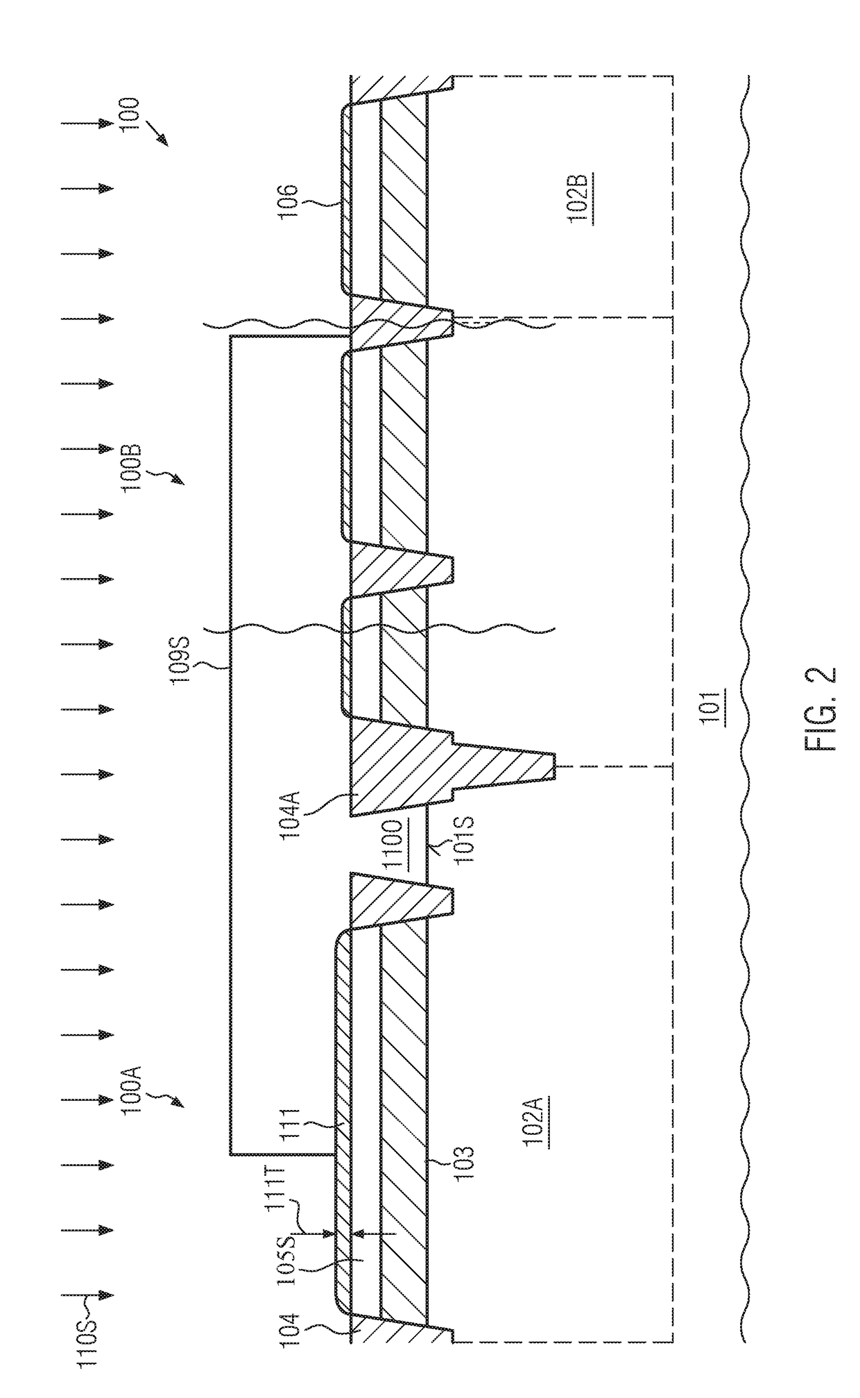
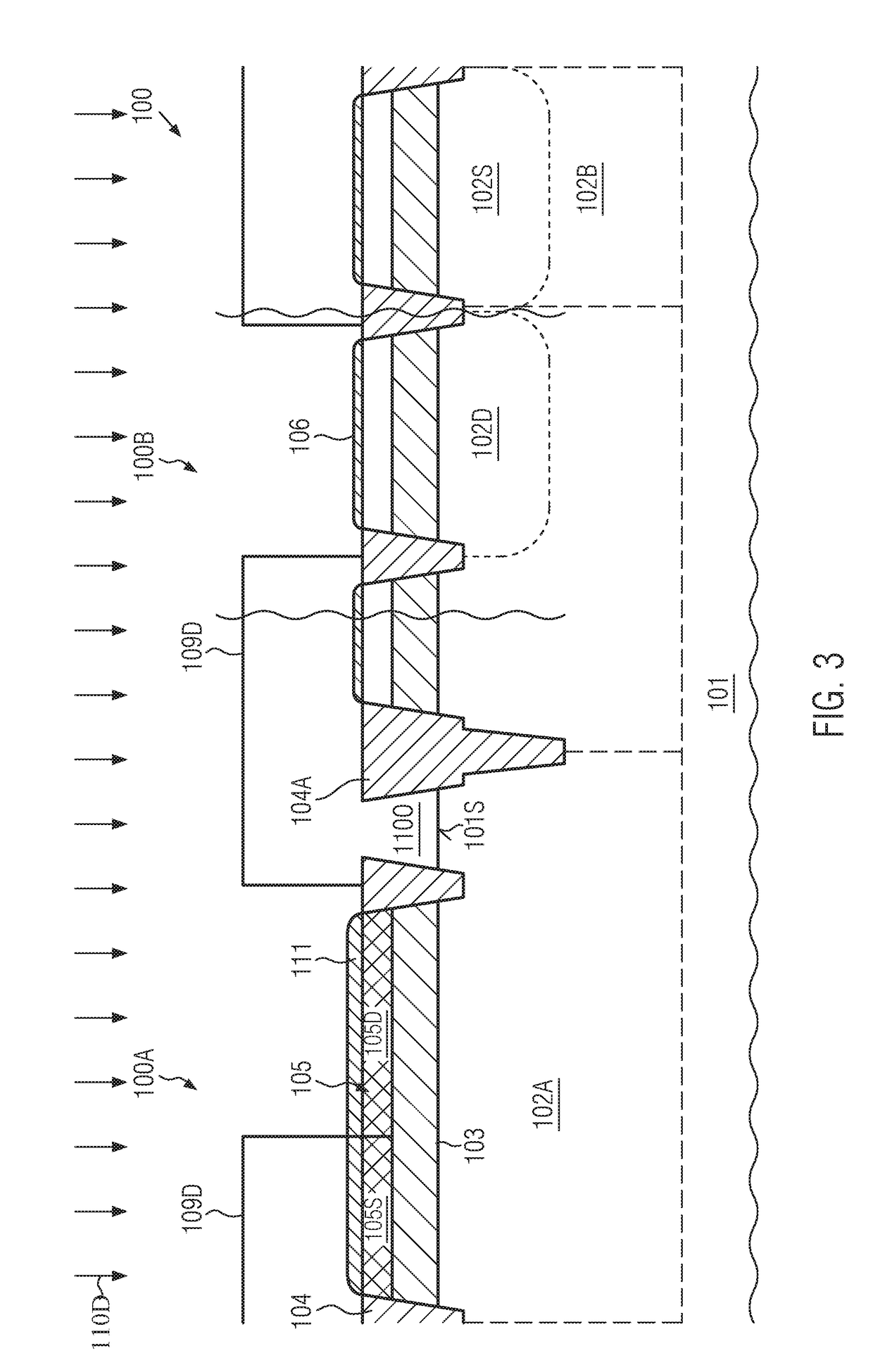
[0027]Various illustrative embodiments of the invention are described below. In the interest of clarity, not all features of an actual implementation are described in this specification. It will of course be appreciated that in the development of any such actual embodiment, numerous implementation-specific decisions must be made to achieve the developers' specific goals, such as compliance with system-related and business-related constraints, which will vary from one implementation to another. Moreover, it will be appreciated that such a development effort might be complex and time-consuming, but would nevertheless be a routine undertaking for those of ordinary skill in the art having the benefit of this disclosure.

[0028]The present disclosure will now be described with reference to the attached figures. Various structures, systems and devices are schematically depicted in the drawings for purposes of explanation only and so as to not obscure the present disclosure with details whic...


PUM


Abstract

A high voltage transistor may be formed on the basis of CMOS techniques for forming sophisticated SOI devices, wherein a fully depleted channel portion may result in low on-resistance and high breakdown voltage. Thus, an LDMOS-type transistor may be formed on the basis of a fully depleted drift region, thereby providing a high degree of scalability and process compatibility with sophisticated CMOS techniques.

Description

BACKGROUND1. Field of the Disclosure[0001]Generally, the present disclosure relates to semiconductor devices and manufacturing techniques in which transistor elements are to be formed on the basis of a semiconductor- or silicon-on-insulator (SOI) architecture, while additionally implementing mechanisms for extending transistor characteristics, in particular, in view of operating voltage and / or on-resistance.2. Description of the Related Art[0002]Significant progress has been made in the field of semiconductor devices, including active circuit elements, such as transistors in the form of field effect transistors, bipolar transistors and the like. In recent developments, critical dimensions of the transistor elements have reached 30 nm and even less in sophisticated planar device architectures, while even further reduced critical dimensions may be implemented in three-dimensional transistor architectures, such as FinFETs and the like. Although reduction of the critical dimensions is b...

Claims


Application Information

Patent Timeline
IPC IPC(8): H01L29/78H01L29/10H01L29/66H01L29/423H01L27/12H01L29/08H01L21/84
CPCH01L29/7824H01L29/1045H01L29/66681H01L29/42368H01L29/1095H01L21/823462H01L29/0865H01L21/84H01L29/0882H01L29/512H01L29/513H01L27/1203H01L21/823418H01L29/78627H01L29/66772H01L29/66628H01L29/665H01L29/517H01L29/1087H01L29/66689H01L27/0629H01L27/088H01L27/04
Inventor YAN, RANCHANG, MING-CHENGMERBETH, THOMAS
Owner GLOBALFOUNDRIES INC
Learn More