
Conductive Particles Comprising Complex Metal Layer With Density Gradient, Method for Preparing the Particles, and Anisotropic Conductive Adhesive Composition Comprising the Particles

Active Publication Date: 2008-05-01
KUKDO ADVANCED MATERIALS CO LTD
View PDF18 Cites 12 Cited by
  • Summary
  • Abstract
  • Description
  • Claims
  • Application Information

AI Technical Summary

Benefits of technology

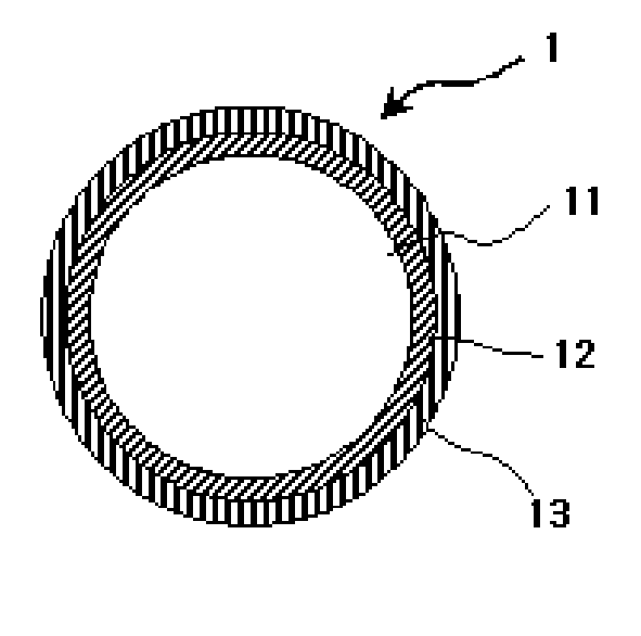
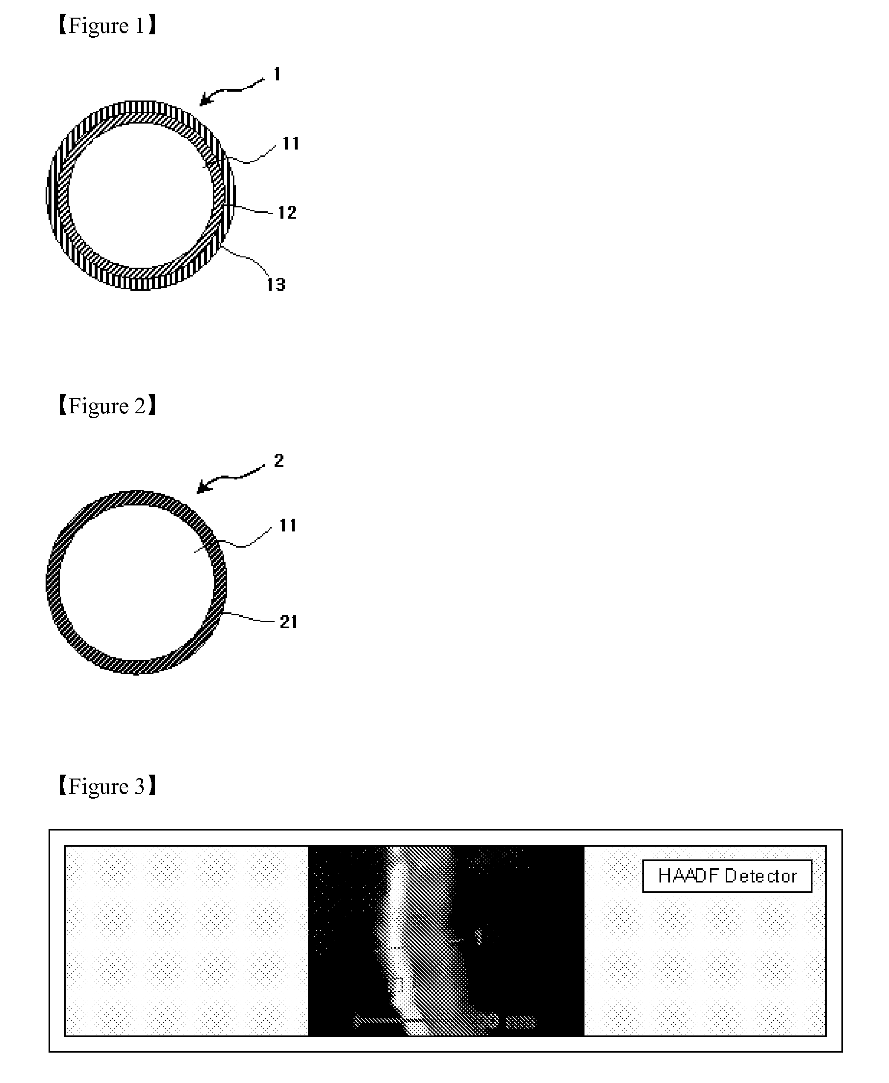
[0015] The conductive particles of the present invention can offer several benefits and advantages. The polymer base particles of the conductive particles of the invention can have a uniform size. In addition, the conductive complex metal plating layer, such as a Ni—Au complex metal plating layer, can have a density gradient so as to achieve superior adhesion to the surface of polymer particles. Further, the conductive particles of the present invention can have high conductivity and can have a readily controlled thickness.
[0018] In accordance with yet another aspect of the present invention, there is provided an anisotropic conductive film comprising the conductive particles wherein the conductive particles are contained in an amount of about 1,000 to about 100,000 count / mm2 in the conductive film. The conductive particles of the anisotropic conductive film of the invention can include a complex metal plating layer and polymer resin base particles, in which the conductive complex metal plating layer can have superior adhesion to the surface of the polymer particles and superior conductivity.
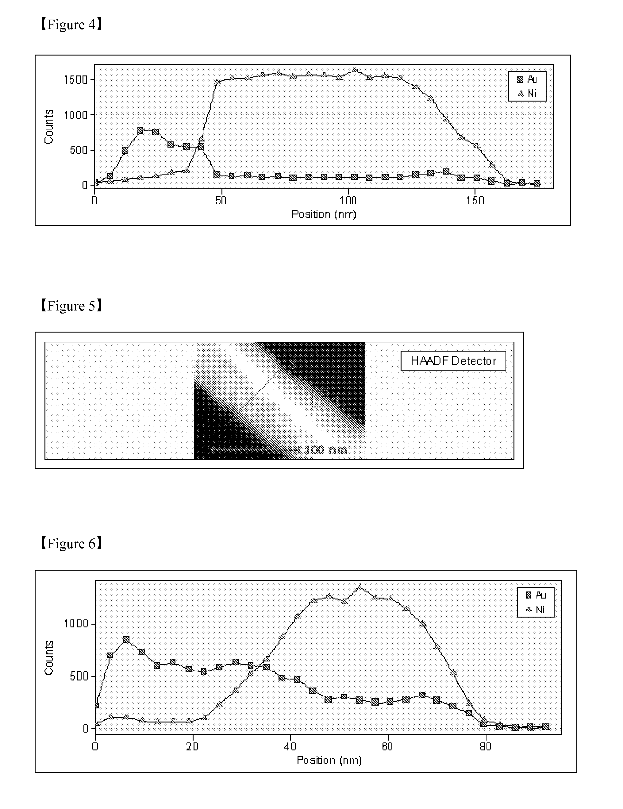
[0019] For the conductive particles having substantially continuous Ni and Au density gradients of the present invention, since the thickness of a hard Ni layer is minimized and a relatively soft Au region and the Ni layer coexist along a certain thickness of the conductive complex metal plating layer, the flexibility and adhesion of the metal plating layer are maintained and at the same time deterioration in electrical connection by rupture can be prevented. In addition, since the conductive particles of the present invention comprise a thinner metal layer than conventional conductive particles, the specific gravity of the final conductive particles can be advantageously lowered, leading to an increase in the number of the conductive particles per unit weight when dispersed in an anisotropic conductive adhesive.
[0020] Furthermore, since filtering after nickel plating in the metal plating process can be omitted, the productivity is improved and loss of metals to be introduced is avoided, thus contributing to cost reduction. Moreover, since peeling of the plating metals and damage to compactness of the plating metals caused due to friction during filtering can be prevented, good conductivity is maintained even after compression for connection, resulting in improved quality of anisotropic conductive films.

Problems solved by technology

When the compressive deformation is continued above 10% or more, the peeling phenomenon leads to the rupture of the Ni layer, resulting in poor electrical connection of an anisotropic conductive film.

Method used


Image

  • Conductive Particles Comprising Complex Metal Layer With Density Gradient, Method for Preparing the Particles, and Anisotropic Conductive Adhesive Composition Comprising the Particles
  • Conductive Particles Comprising Complex Metal Layer With Density Gradient, Method for Preparing the Particles, and Anisotropic Conductive Adhesive Composition Comprising the Particles
  • Conductive Particles Comprising Complex Metal Layer With Density Gradient, Method for Preparing the Particles, and Anisotropic Conductive Adhesive Composition Comprising the Particles

Examples


examples 1 to 4

(1) Selection of Particles

[0056] Polydivinylbenzene (PDVB) polymer particles are selected as base particles. Each of the polymer particles has a CV value of 4.5% and an average particle size (8.9 μm, 5.2 μm, 4.1 μm and 3.7 μm) indicated in Table 1 below.

TABLE 1Example No.Particle size of polymer (μm)Example 18.9Example 25.2Example 34.1Example 43.7

(2) Pretreatments

[0057] 20 g of each of the PDVB particles is dipped in a 2% surfactant solution for 10 minutes to defat the surface of the PDVB particles. The surfactant solution can be readily prepared by processes well known to those skilled in the art. Thereafter, the defatted PDVB particles are etched by dipping the particles in a mixed solution containing 10 g / L chromic acid and 400 g / L sulfuric acid for 10 minutes to form anchors on the PDVB particles, dipped in an aqueous tin (II) chloride solution (1 g / L) for 3 minutes, filtered, and washed to catalyze and activate the surface of the polymer particles. The collected polymer par...

examples 5 to 10

(1) Production of Anisotropic Conductive Films

[0064] In Examples 5 to 10, anisotropic conductive films are produced using conductive particles having a continuous density gradient of Ni and Au, in accordance with the following procedure.

[0065] 15 parts by weight of a bisphenol A epoxy resin having an epoxy equivalent of 6,000 and 7 parts by weight of 2-methylimidazole as a curing agent are dissolved in a mixed solvent of toluene and methyl ethyl ketone, after which 2 to 15 wt % of conductive particles and a silane-based coupling agent are dispersed in the solution. The conductive particles are prepared in the same manner as in Example 1, except that the content and size are changed to those indicated in Table 4 below. The resulting dispersion is coated on a PET release film, and dried to produce a 25 μm thick anisotropic conductive adhesive film.

[0066] An anisotropic conductive film is produced from the anisotropic conductive adhesive film so as to have the following dimensions. ...


PUM

PropertyMeasurementUnit
Fractionaaaaaaaaaa
Fractionaaaaaaaaaa
Thicknessaaaaaaaaaa

Abstract

Disclosed herein are anisotropic conductive particles having superior electrical reliability which are useful as materials for electrical connection structures. Further disclosed is a method for preparing conductive particles comprising polymer resin base particles and a conductive complex metal plating layer formed on the surface of the base particles wherein the conductive complex metal plating layer has a substantially continuous density gradient and can include nickel (Ni) and gold (Au).

Description

CROSS-REFERENCE TO RELATED APPLICATIONS [0001] This non-provisional application is a continuation-in-part application of PCT Application No. PCT / KR2005 / 002557, filed Aug. 5, 2005, pending, which designates the U.S. and which is hereby incorporated by reference in its entirety, and from Korean Patent Application No. 10-2005-0060225, filed Jul. 5, 2005, which is also hereby incorporated by reference in its entirety.FIELD OF THE INVENTION [0002] The present invention relates to anisotropic conductive particles and methods for preparing conductive particles. BACKGROUND OF THE INVENTION [0003] Conductive resin materials and plastic materials are currently used for electrical connection between minute sites of electronic devices, e.g., between ITO electrodes and driving LSIs, between LSI chips and circuit boards, and between micro-pattern electrode terminals in liquid crystal display (LCD) panels. In particular, anisotropic conductive films are used to ensure electrical contact between el...

Claims


Application Information

Patent Timeline
IPC IPC(8): B32B5/16B05D3/04
CPCH05K3/323H05K2201/0221Y10T428/2991Y10T428/2998Y10T428/25H05K2201/0233C08J3/12
Inventor BAE, TAE SUBPARK, JIN GYUJUN, JUNG BAELEE, JAE HOPARK, JUNG ILLEE, SANG WOON
Owner KUKDO ADVANCED MATERIALS CO LTD
Learn More