Manufacturing method of a complex geometry panel in prepreg composite material

a composite material and complex geometry technology, applied in the field of manufacturing methods of complex geometry panels in prepreg composite materials, can solve the problems of unsatisfactory application of conventional thermoforming and pressing techniques directly to complex geometry panels, method that cannot be applied to panels of closed contour such as cylindrical or conical panels, etc., to achieve maximum mechanical and structural integrity and maximum precision

Inactive Publication Date: 2010-05-06
AIRBUS OPERATIONS SL
View PDF11 Cites 18 Cited by
  • Summary
  • Abstract
  • Description
  • Claims
  • Application Information

AI Technical Summary

Benefits of technology

[0001]The general objective problem that this invention relates to is to provide a manufacturing method for structural panels of complex geometry and low weight, ensuring that the panels obtained have: maximum mechanical and structural integrity and maximum precision in terms of dimensional tolerance.
[0006]The reason for the panels having a complex geometry is that, with the incorporation of particular reliefs in said panels, such as undulations or grooves, the desirable technical effect can be achieved of optimizing the structural or mechanical behavior of a flat panel, for example eliminating the warping or in general increasing the resistance to stresses in the direction normal to the surface of the panel, thereby making up for the need to incorporate into the flat panel other reinforcing elements not involved in the panel such as stringers or stiffeners, which is the solution that predominates nowadays. This solution of incorporating auxiliary reinforcing elements into a flat panel has the major drawback that its installation is complicated, owing to the large amount of auxiliary pieces that it requires such as rivets or other attachment elements, fastenings, etc., as well as having an adverse effect on the weight of structure. Therefore, with the integration of said reliefs in the actual structure constituting the complex geometry panel, the technical advantages of reducing the manufacturing time of the structural panel, reducing its cost and reducing the weight of the structure, improving the mechanical and structural behavior of the panel are achieved.
[0007]The solution provided by the present invention is based on the conventional processing of prepreg composite material which, as has been defined earlier, is carried out on sufficiently flat mold surfaces. In particular, and without limitation, the invention is conceived for the technique in which the prepreg is processed automatically, via a head which sweeps the surface of the mold spreading the material, this is the case of processes known in the art as automatic tape lay-up or fiber placement. The automatic processing of prepreg provides the additional advantages, compared to manual processing, of improving the production chain and lowering costs, due to reducing the manufacturing time and reducing the waste material, along with providing a greater precision, due to the uniformity of the pressures in the spreading of the prepreg and the compaction of the stack.

Problems solved by technology

But said method does not permit its application to prepregs whose size is sufficiently large and / or in which the pre-form remains trapped by an exterior contour.
Equally, this method would not be applicable to panels of closed contour such as cylindrical or conical panels.
On account of the above factors, the application of the conventional thermoforming and pressing technique directly to complex geometry panels turns out not to be satisfactory.
Moreover, even if the pre-form were to be of sufficiently small size and had an open contour it would still not be possible to use this conventional technique to obtain certain pieces with sufficiently complex shapes, or complex geometry panels, with precision in terms of dimensional tolerance, because the appearance of creases and folds derived from the effect of distorting the layers of the prepreg and of the fibers during the forming would be unavoidable.
These defects in the dimensional tolerance can lead to other derived defects to the detriment of the mechanical and structural integrity of the piece to be obtained such as for example vulnerability to the delamination of the prepreg, due to the increase in the probability of the appearance of cavities and stress concentration points as a consequence.

Method used


Image

  • Manufacturing method of a complex geometry panel in prepreg composite material
  • Manufacturing method of a complex geometry panel in prepreg composite material
  • Manufacturing method of a complex geometry panel in prepreg composite material

Examples


Embodiment Construction

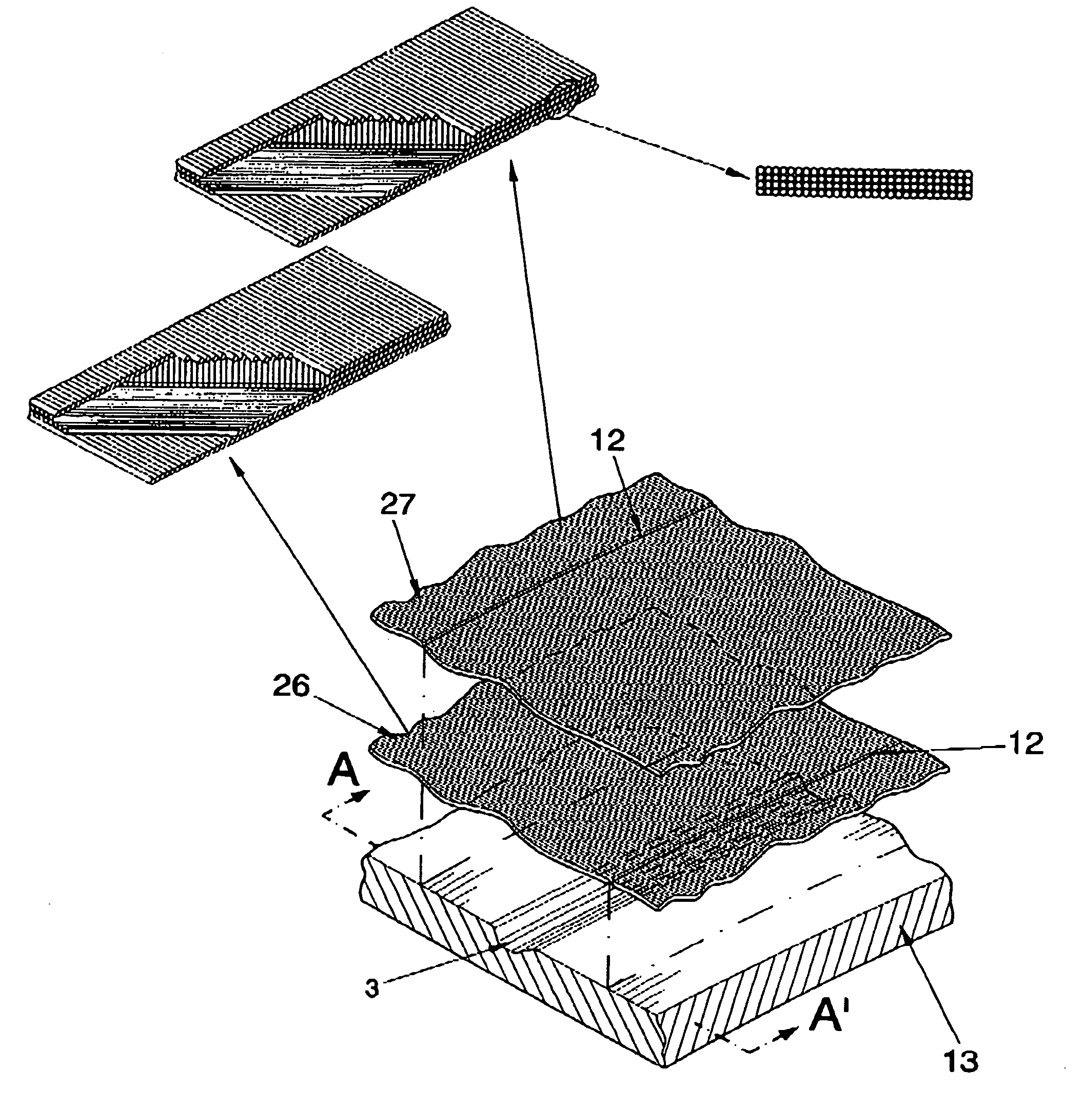
[0023]As will be described below, the characteristics of the present invention determine that the advocated method, unlike the known art, is applicable on an unlimited basis to obtaining panels in prepreg composite material of sufficiently large size and to obtaining complex geometry panels, having reliefs of more complex shapes than those that can be obtained with the current art. Additionally, the method permits manufacture by means of the automatic pre-impregnating process, using techniques known as “fiber placement” and “automatic tape lay-up”, permitting a high production chain and low cost and assuring that the panels obtained have maximum mechanical and structural integrity and maximum precision in terms of dimensional tolerance.

[0024]The method comprises the following stages: a first stage, known as “stacking”, a second stage known as “forming”, and a third stage known as “finishing”.

[0025]In the first stage, the prepreg is spread over a mold giving rise to the stack. Unlike...


PUM

PropertyMeasurementUnit
temperatureaaaaaaaaaa
pressureaaaaaaaaaa
weightaaaaaaaaaa

Abstract

The method comprises: a first stage in which the layers of the prepreg are spread over a mold having cavities corresponding to reliefs (3) of the complex geometry panel (1) to be obtained, the layers of prepreg presenting lines of discontinuity (12) in the vecinity of the reliefs (3); a second stage in which the stack (11) is done by application of a cycle of pressure and temperature; and a third stage of finishing of the panel to be obtained, comprising the curing of the prepreg.

Description

OBJECT OF THE INVENTION[0001]The general objective problem that this invention relates to is to provide a manufacturing method for structural panels of complex geometry and low weight, ensuring that the panels obtained have: maximum mechanical and structural integrity and maximum precision in terms of dimensional tolerance.[0002]In the present invention, “panel” is understood to be a piece of very small thickness in comparison with the surface over which it extends, or characteristic surface, this characteristic surface being able to have an open or closed contour (e.g., cylinders or cones are regarded as closed contour surfaces).[0003]The low weight of the panel to obtain as well as its structural functionality required directs the application of the invention towards panels manufactured in prepreg composite materials, as stated in the title of this descriptive specification.[0004]Prepreg material essentially consists of a set of reinforcing fibers impregnated in a resin matrix and...

Claims


Application Information

Patent Timeline
Patent Type & Authority Applications(United States)
IPC IPC(8): B32B7/04B32B7/08
CPCB29C70/46B29D99/0014B32B3/30B32B5/26B32B7/08B32B7/03B32B2260/021B32B2260/046B32B2307/514B32B2607/00B32B7/12B29C70/304B29C70/461B29C70/345
Inventor SANCHEZ-BRUNETE ALVAREZ, DESIDERIO
Owner AIRBUS OPERATIONS SL
Why Eureka
Try Eureka