
Apparatus and process for gas sensor control

Active Publication Date: 2010-05-06
NGK SPARK PLUG CO LTD
View PDF3 Cites 9 Cited by
  • Summary
  • Abstract
  • Description
  • Claims
  • Application Information

AI Technical Summary

Benefits of technology

[0007]However, when the abnormality is detected, the above-mentioned diagnostic system inhibits the supply of current to the heater, so that the gas sensor is cooled and foreign substance such as carbon may adhere to the surface of the sensor (the surface of the sensing element). The matter adhering to the gas sensor might obstruct the function of the gas sensing element when the normal condition is regained and the normal heater control mode is restarted. In view of such a problem, it is an object of the present invention to provide technique, such as gas sensor control apparatus and / or process, adequate for preventing improper overheating of gas sensor due to trouble such as wiring disconnection, and enabling restoration of a normal gas sensor operation. It is another object of the present invention to provide technique, such as gas sensor control apparatus and / or process, adequate for preventing improper overheating of gas sensor due to overheating of the heater when such a condition continues that an impedance of the gas sensor detected for wiring disconnection of the cell or the like, shows exceedingly high level, and preventing foreign substance such as carbon from adhering to the surface of the sensor by cooling the gas sensor without stopping the supply of current to the heater.

Problems solved by technology

However, when the abnormality is detected, the above-mentioned diagnostic system inhibits the supply of current to the heater, so that the gas sensor is cooled and foreign substance such as carbon may adhere to the surface of the sensor (the surface of the sensing element).
The matter adhering to the gas sensor might obstruct the function of the gas sensing element when the normal condition is regained and the normal heater control mode is restarted.

Method used


Image

  • Apparatus and process for gas sensor control
  • Apparatus and process for gas sensor control
  • Apparatus and process for gas sensor control

Examples


Embodiment Construction

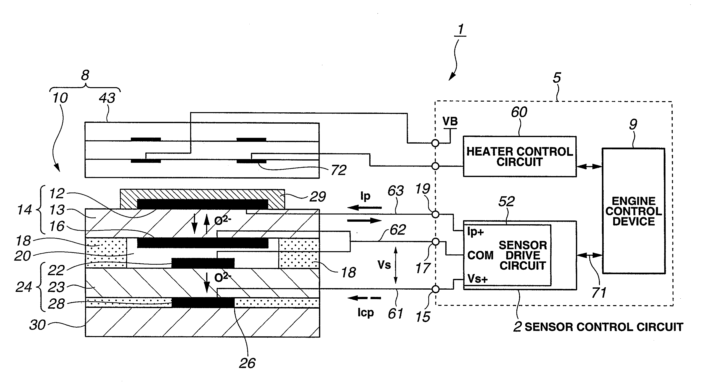
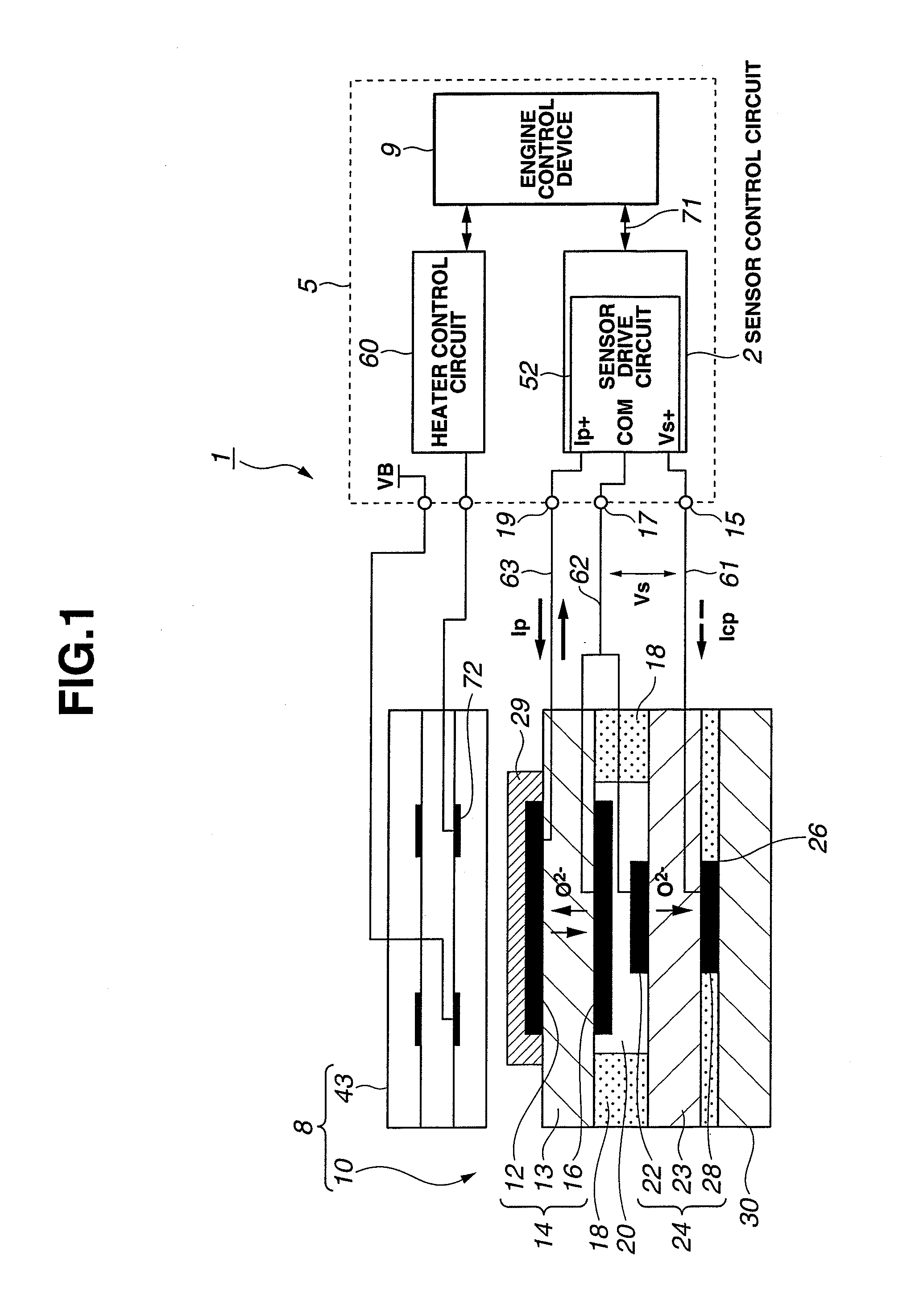
[0016]FIG. 1 schematically shows a control system 1 including a gas sensor control unit (electronic control unit ECU) 5. The control system 1 of this example is constructed as an internal combustion engine control system performing various control operations to control one or more operating conditions of an internal combustion engine (engine), and operations for sensing a specified gas component (such as oxygen) in a measurement gas (such as exhaust gas mixture) to be examined.

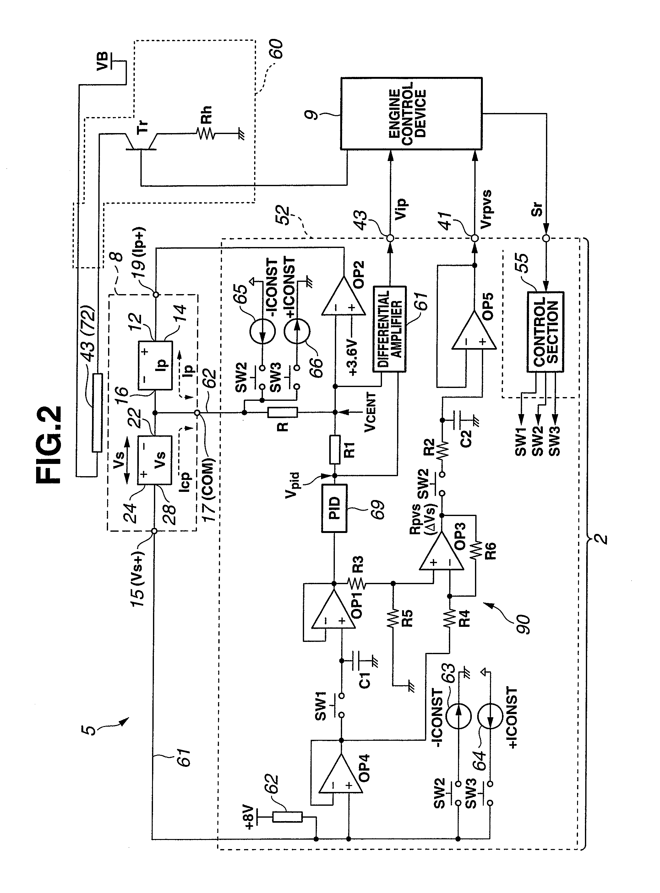
[0017]This control system 1 includes the electronic control unit 5 and a gas sensor 8 attached to an exhaust pipe of the engine. Electronic control unit 5 includes a sensor control circuit 2 for controlling the gas sensor 8 (sensing element 10), an engine control device 9 (hereinafter referred to as engine CPU 9), and a heater control circuit 60 for controlling a heater (or heating element) 43. The sensor control circuit 2 includes a sensor drive circuit 52. The engine control device 9 is connected with the he...


PUM


Abstract

A gas sensor control apparatus includes a heater regulating section to control the supply of electricity to a heater included in a gas sensor, an impedance sensing section to sense an impedance of a cell of the gas sensor, and an impedance condition examining section to examine whether the sensed impedance is greater than or equal to a predetermined abnormality judging threshold. The control apparatus further includes a voltage condition examining section to examine whether a maximum effective voltage is applied to the heater, when the impedance is above the predetermined abnormality judging threshold, a duration measuring section to examine whether an application time duration of the maximum effective voltage becomes equal to or longer than a predetermined heater overheat preventing time, and a voltage decreasing section to decrease the heater application voltage to such a lower effective voltage as to hold the temperature of the cell higher than or equal to 500° C. when the application time duration reaches the predetermined heater overheat preventing time.

Description

BACKGROUND OF THE INVENTION[0001]The present invention relates to apparatus and / or process for controlling a gas sensor, such as a gas sensor including at least one cell which includes a solid electrolyte member and a pair of electrodes formed on the solid electrolyte member. Specifically, the present invention relates to a technique for sensing the impedance of a cell of the gas sensor, and controlling the supply of electricity to a heater of the gas sensor in accordance with the sensed cell impedance.[0002]A gas sensor, such as oxygen sensor and air fuel ratio sensor, is widely used for an internal combustion engine for a motor vehicle or other applications, to improve the fuel consumption and control the combustion. Furthermore, in conjunction with the environmental concerns and tightening of regulations for limiting exhaust emissions of motor vehicles, the demand for reducing the amount of nitrogen oxides (NOx) in the exhaust gas mixture increases and drives the development of a...

Claims


Application Information

Patent Timeline
IPC IPC(8): G01F1/64G01N27/26
CPCG01N27/4067
Inventor KATO, AKIYOSHISUZUKI, KEIJI
Owner NGK SPARK PLUG CO LTD
Learn More