
Piezoelectric element and method for manufacturing the same, liquid-ejecting head and method for manufacturing the same, and liquid-ejecting apparatus

Active Publication Date: 2010-05-06
SEIKO EPSON CORP
View PDF2 Cites 2 Cited by
  • Summary
  • Abstract
  • Description
  • Claims
  • Application Information

AI Technical Summary

Benefits of technology

[0008]An advantage of some aspects of the invention is that it provides a piezoelectric element that deforms as much as possible during startup and has a low deformation reduction rate that depends on the number of operations performed and a method for manufacturing the piezoelectric element, a liquid-ejecting head and a method for manufacturing the liquid-ejecting head, and a liquid-ejecting apparatus.
[0020]According to an aspect of the invention, the piezoelectric film having a composition satisfying the relationship of Zr / (Ti+Zr)>Ti / (Ti+Zr) can exhibit a large deformation during startup (maximum deformation), and the polarization-electric field hysteresis loop having a Pm / 2Pr of 1.95 or more and a Vc(−) of −1.75 V or more (wherein Pm denotes saturation polarization, Pr denotes remanent polarization, and Vc(−) denotes a negative coercive electric field intensity) allows the deformation reduction rate that depends on the number of operations performed to be reduced.

Problems solved by technology

However, it is also known that an excessively high Ti / Zr ratio results in a high deformation reduction rate that depends on the number of operations performed.
Thus, there is a trade-off between a large initial deformation and a low deformation reduction rate, and it is difficult to realize both a large initial deformation and a low deformation reduction rate to a high degree.

Method used


Image

  • Piezoelectric element and method for manufacturing the same, liquid-ejecting head and method for manufacturing the same, and liquid-ejecting apparatus
  • Piezoelectric element and method for manufacturing the same, liquid-ejecting head and method for manufacturing the same, and liquid-ejecting apparatus
  • Piezoelectric element and method for manufacturing the same, liquid-ejecting head and method for manufacturing the same, and liquid-ejecting apparatus

Examples


Embodiment Construction

[0031]Embodiments of the invention will be described below with reference to the accompanying drawings. Although the following preferred embodiments of the invention include various limitations, unless otherwise specified, the scope of the invention is not limited to these embodiments. In the following embodiments, a liquid-ejecting apparatus according to an aspect of the invention is exemplified by an ink jet printer (hereinafter referred to simply as a printer) that includes an ink jet print head (hereinafter referred to simply as a print head), which is one type of liquid-ejecting heads.

[0032]First, a print head 1 will be described below.

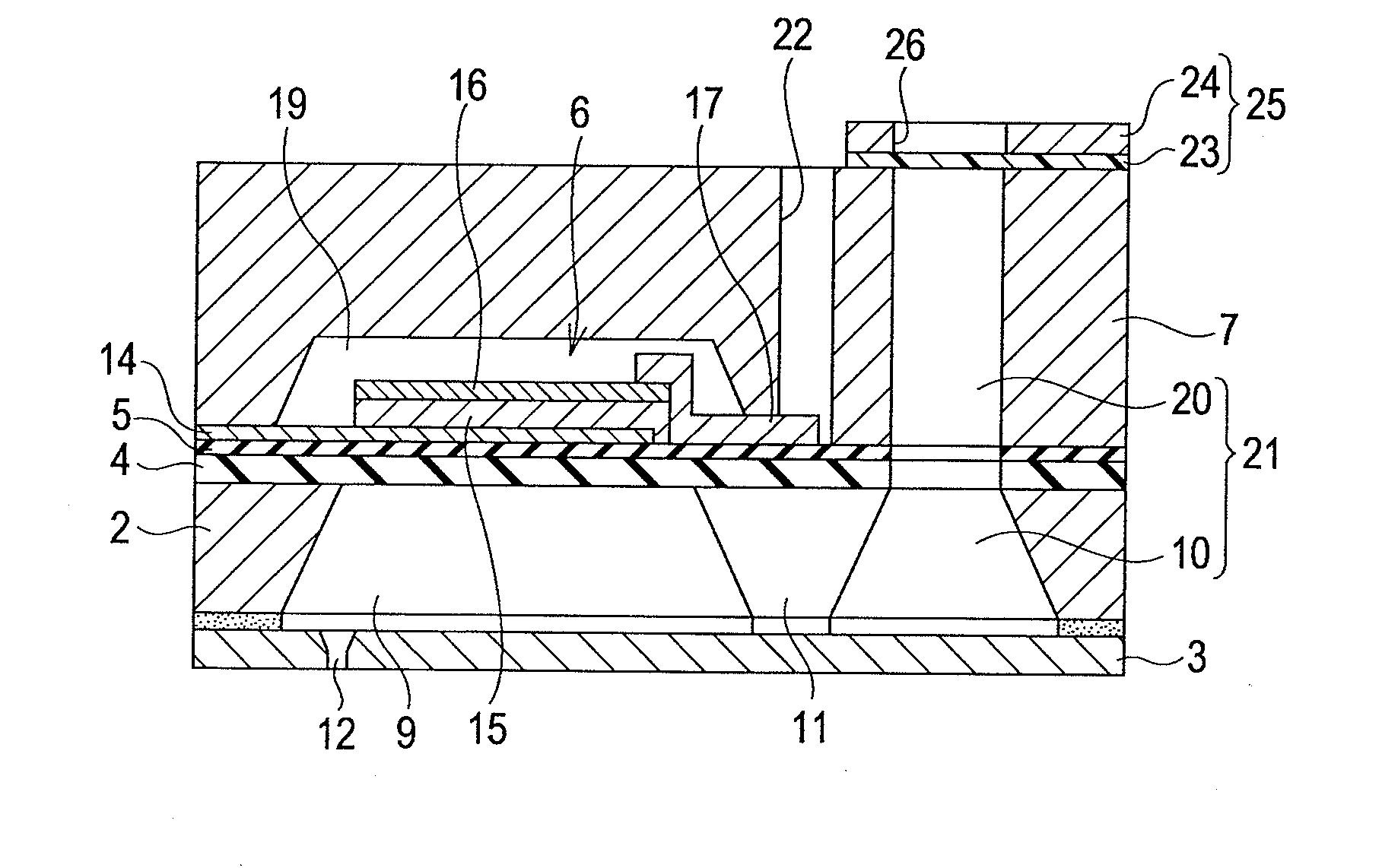
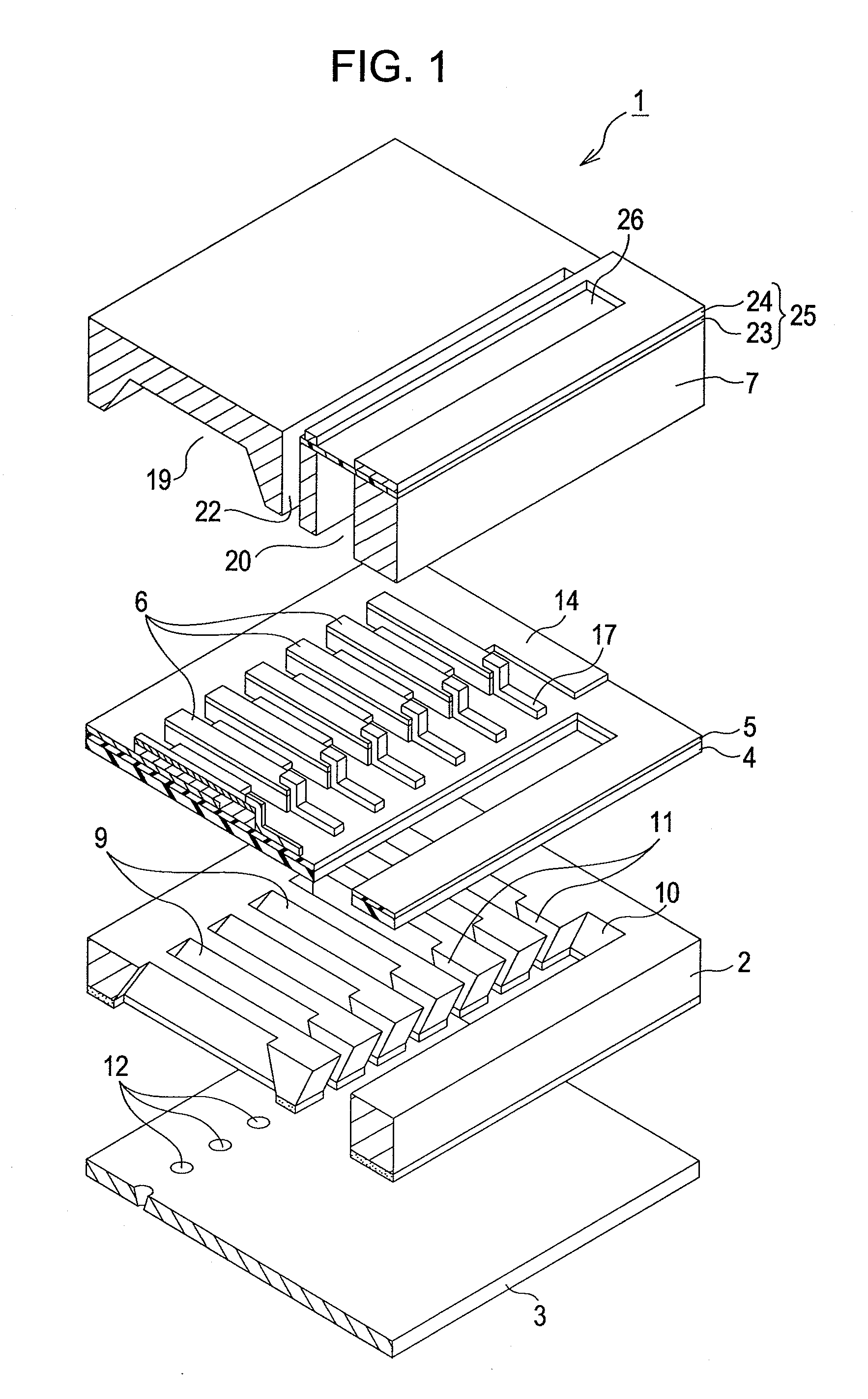
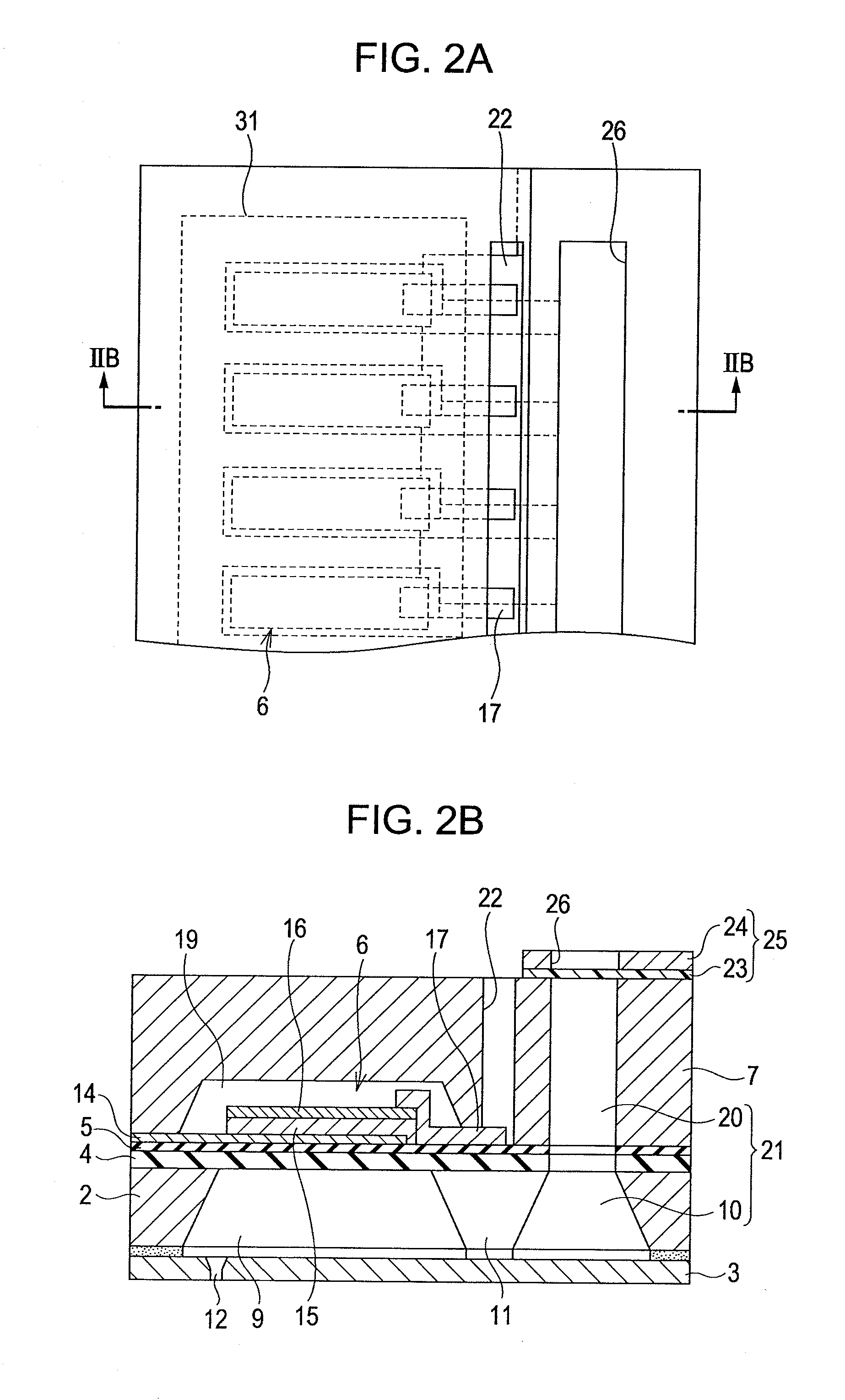
[0033]FIG. 1 is an exploded perspective view of a print head 1 according to the present embodiment. FIG. 2A is a fragmentary plan view of the print head 1, and FIG. 2B is a cross-sectional view taken along the line IIB-IIB in FIG. 2A. The print head 1 includes a flow-passage-forming substrate 2, a nozzle plate 3, an elastic film 4, an insulator f...


PUM

PropertyMeasurementUnit
Piezoelectricityaaaaaaaaaa

Abstract

A piezoelectric element includes a piezoelectric film containing lead (Pb), zirconium (Zr), and titanium (Ti). The piezoelectric film has a composition satisfying the relationship of Zr / (Ti+Zr)>Ti / (Ti+Zr) and has a polarization-electric field hysteresis loop having a Pm / 2Pr of 1.95 or more and a Vc(−) of −1.75 V or more, wherein Pm denotes saturation polarization, Pr denotes remanent polarization, and Vc(−) denotes a negative coercive electric field intensity.

Description

[0001]This application claims priority to Japanese Patent Applications Nos. 2008-283372, filed Nov. 4, 2008 and 2009-214140, filed Sep. 16, 2009 the entireties of which are incorporated by reference herein.BACKGROUND[0002]1. Technical Field[0003]The present invention relates to a piezoelectric element for use as a liquid-ejecting head drive, such as an ink jet print head drive, and a method for manufacturing the piezoelectric element, a liquid-ejecting head and a method for manufacturing the liquid-ejecting head, and a liquid-ejecting apparatus. More particularly, the invention relates to a piezoelectric element that deforms as much as possible during startup and exhibits a small time-dependent decrease in deformation, and a method for manufacturing the piezoelectric element, a liquid-ejecting head and a method for manufacturing the liquid-ejecting head, and a liquid-ejecting apparatus.[0004]2. Related Art[0005]Liquid-ejecting apparatuses include a liquid-ejecting head and eject var...

Claims


Application Information

Patent Timeline
IPC IPC(8): B41J2/045H01L41/16H04R17/00B41J2/055B41J2/135B41J2/14B41J2/145B41J2/16H01L41/09H01L41/187H01L41/22H01L41/318H01L41/43
CPCB41J2/161B41J2/1646B41J2002/14241B41J2002/14419B41J2202/03H01L41/1876H01L41/318H01L41/0973Y10T29/42H10N30/2047H10N30/8554H10N30/078
Inventor KURIKI, AKIRASUMI, KOJISAWASAKI, TATSUOTORIMOTO, TATSUROTAKABE, MOTOKI
Owner SEIKO EPSON CORP
Learn More