Filter frame and camera filter unit

a filter frame and filter unit technology, applied in the field of camera filter units, can solve the problems of difficult to reduce the width l of the conventional filter frame, the front end portion of the filter frame gets in the angle of field, etc., and achieve the effect of improving the structure for mounting and small siz

Active Publication Date: 2010-05-06
TSUSO
View PDF0 Cites 16 Cited by
  • Summary
  • Abstract
  • Description
  • Claims
  • Application Information

AI Technical Summary

Benefits of technology

[0012]An object of the present invention is to provide a filter frame of small width by improving the structure for mounting an optical filter to a filter frame, and also a camera filter unit of small width comprising this filter frame.
[0020]In the filter frame of the present invention, the filter-holding ring is concentrically fixed to the internal side of the cylindrical component, and the optical filter is concentrically held in the internal side of the filter-holding ring. In other words, the filter-holding ring, which is a member for mounting the optical filter to the filter frame, is not disposed in front of or behind the optical filter, but is concentrically disposed in the internal side of a cylindrical part (the external peripheral side of the optical filter). As a result, the width dimension (the longitudinal dimension) of the filter frame can be made smaller than when a retaining ring or another mounting tool is used in order to hold the optical filter.
[0022]Furthermore, in the present invention, the optical filter can be held reliably because a sufficient mounting area can be ensured for the filter-holding ring within the width dimension of the external peripheral surface of the optical filter.
[0025]The front stopper can be a protuberance which protrudes inward from the front end edge of the filter-holding ring, and the rear stopper can be an annular crimp formed by inwardly crimping the rear end edge portion in the filter-holding ring. The optical filter can thus be mounted to the filter frame in a state of being fixed to the filter-holding ring, and the operation of fixing the optical filter to the filter frame is therefore made easier. The number of components can also remain low because there is no need to prepare any members other than the filter-holding ring in order to fix the optical filter to the filter-holding ring.
[0026]In this case, the cylindrical component preferably has in the rear side of the crimp an annular part having an annular end surface protruding farther inward than the crimp. The crimp can thus be covered by the annular part, and the aesthetic appearance of the camera filter unit is therefore improved. In this case, the frame-side male thread is also preferably formed in the external peripheral surface of the annular part.
[0028]Next, the front end surface of the protuberance is preferable a diffuse reflection surface. External light that would permeate into the filter frame from the external periphery at the front end of the filter frame is thus diffusely reflected by the front end surface of the protuberance of the filter-holding ring. Therefore, in cases in which the camera filter unit is mounted to the distal end portion of the taking lens of the camera, it is possible to reduce the occurrence of instances in which external light is reflected into the screen of the camera.

Problems solved by technology

Therefore, when the filter frame holding the optical filter is long in terms of its longitudinal dimension, there is a problem in that the front end portion of the filter frame gets in the angle of field of the taking lens.
Therefore, there is a problem in that it is difficult to reduce the width L of the conventional filter frame 101 (to reduce the dimension L in the direction of the center axis line).

Method used


Image

  • Filter frame and camera filter unit
  • Filter frame and camera filter unit
  • Filter frame and camera filter unit

Examples


embodiment 1

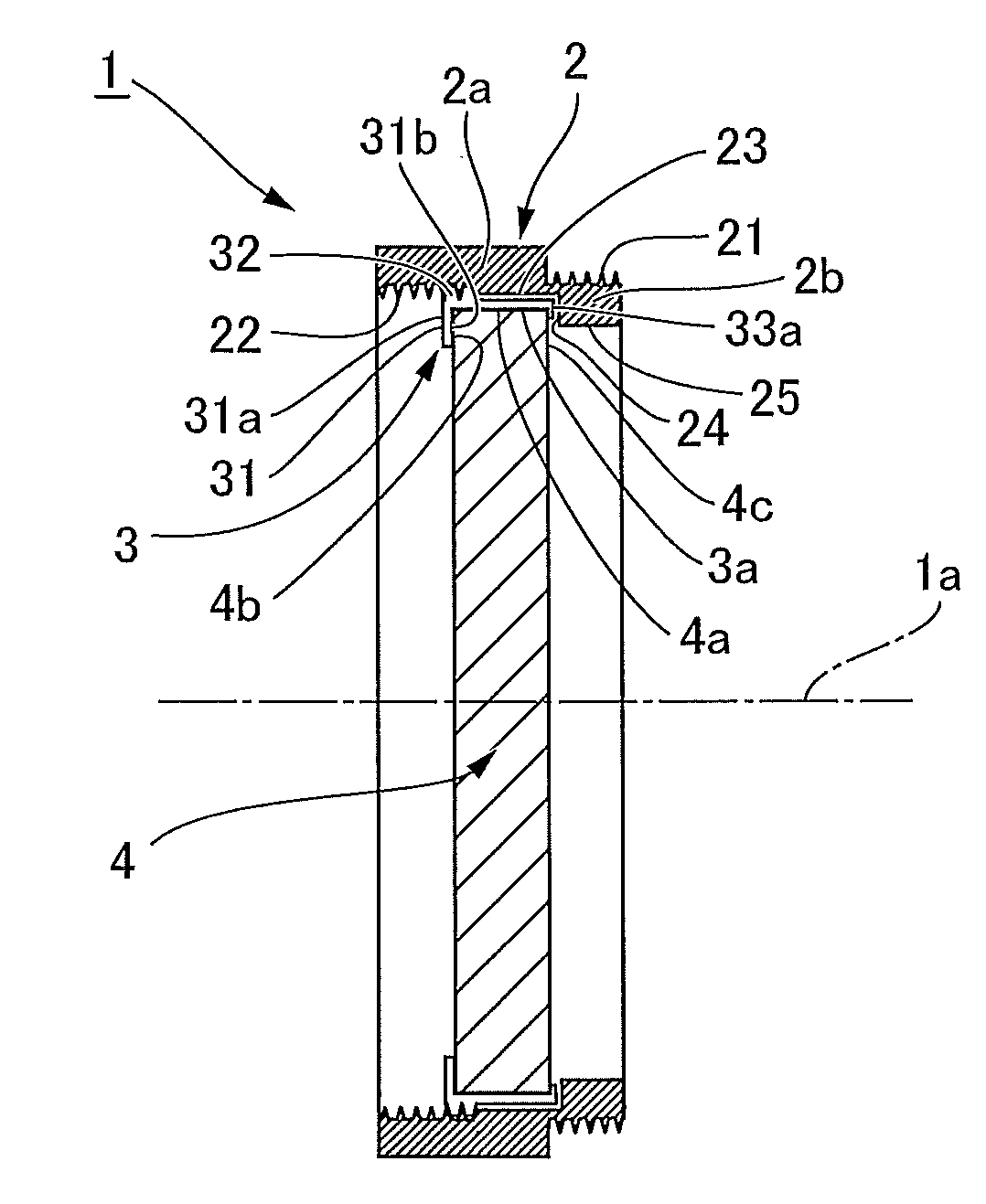
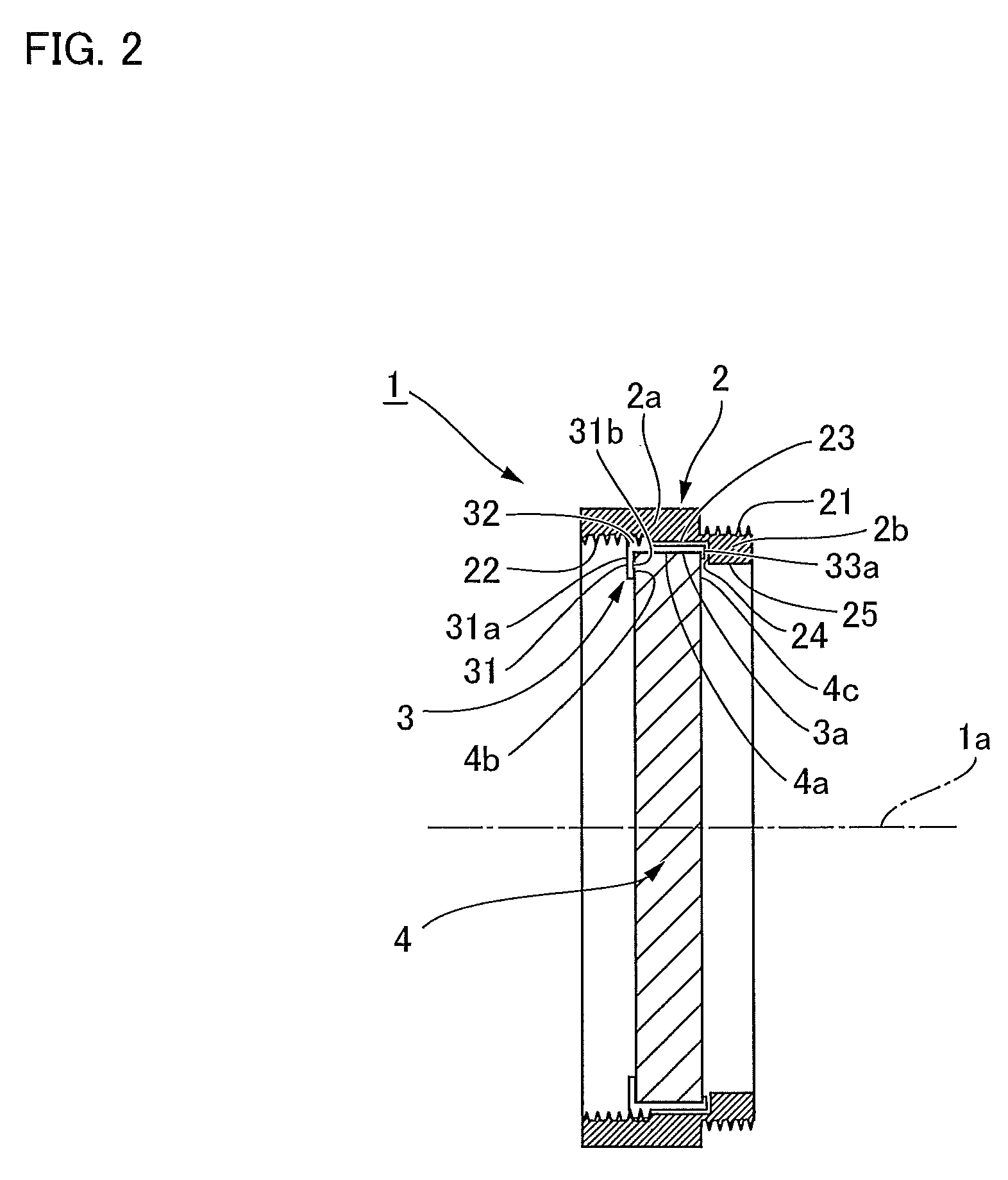
[0036]FIG. 1 is a perspective view of a camera filter unit according to Embodiment 1, and FIG. 2 is a schematic longitudinal cross-sectional view thereof. The camera filter unit 1 has a filter frame 2, and a discoid optical filter 4 held concentrically on the internal side of the filter frame 2, as shown in the drawings. The filter frame 2 has a cylindrical component 2a, and a filter-holding ring 3 concentrically and threadably fixed into the internal side of the cylindrical component 2a. The width of the cylindrical component 2a (the dimension in the direction of a center axis 1a of the filter frame) is significantly greater than the widths of the filter-holding ring 3 and the optical filter 4.

[0037]A small-diameter annular part 2b is coaxially and integrally formed in the rear end portion of the cylindrical component 2a, as can be seen from FIG. 2. A frame-side male thread 21 is formed in the small-diameter external peripheral surface of the annular part 2b. The frame-side male th...

embodiment 2

[0047]FIG. 4 shows a modification of the filter frame 2 according to Embodiment 1, and the mounting structure of the optical filter 4 in relation to the filter frame 2 is slightly different from Embodiment 1. Therefore, corresponding components are denoted by the same numerical symbols in FIG. 4, and the corresponding components are not described hereinbelow.

[0048]In the filter frame 2A of the camera filter unit 1A, the filter-holding ring 3A does not have a rear end edge portion 33 protruding farther rearward than the rear end edge 4c of the optical filter 4. Either the rear end 34 of the filter-holding ring 3A is positioned in the same position as the rear end edge 4c of the optical filter 4, or the rear end 34 of the filter-holding ring 3A is positioned in front of the rear end edge 4c of the optical filter 4.

[0049]In the present example, the annular end surface 24 in the annular part 2b at the rear of the cylindrical component 2a of the filter frame 2 functions as a rear stopper...


PUM


Abstract

In a camera filter unit having a small longitudinal width, the camera filter unit (1) comprises a filter frame (2) having a cylindrical component (2a) and a filter-holding ring (3), and an optical filter (4). The optical filter (4) is fixed to an internal side of the filter-holding ring (3) in a state of being held from the front and the rear between a protuberance (31) formed in the filter-holding ring (3) and a crimp (33a). The filter-holding ring (3) is fixed to the internal side of the cylindrical component (2a) by a ring-side male thread (32) being screwed into a female thread (22) of the filter frame (2). The filter-holding ring (3) for holding the optical filter (4) is disposed concentrically between the cylindrical component (2a) and the optical filter (4), and the longitudinal dimension of the filter frame (2) can therefore be made smaller than when the member for holding the optical filter is mounted to the cylindrical component (2a) in a state of being aligned with the optical filter (4) in the axial direction.

Description

BACKGROUND OF THE INVENTION[0001]1. Field of the Invention[0002]The present invention relates to a camera filter unit, and particularly to a technique for improving a filter frame for holding an optical filter.[0003]2. Description of the Related Art[0004]The configuration shown in FIG. 5 is a known example of a camera filter unit mounted to a lens tube of a taking lens of a camera. This type of a camera filter unit is disclosed in JP-A 11-271840.[0005]A camera filter unit 100 comprises a discoid optical filter 103, and a cylindrical filter frame 101 which holds the optical filter 103 on the internal side, as shown in FIG. 5. A male thread 101b is formed in the external peripheral surface of the filter frame 101 in an area of a specified width forward from the rear end edge. A female thread 101a is formed in the internal peripheral surface of the filter frame 101 in an area of a specified width rearward from the front end edge.[0006]The male thread 101b in the external peripheral sur...

Claims


Application Information

Patent Timeline
Patent Type & Authority Applications(United States)
IPC IPC(8): G03B11/00
CPCG03B11/00
Inventor KOBAYASHI, HIDEO
Owner TSUSO
Why Eureka
Try Eureka