
Method, system and device for realizing data transmission extension in passive optical network

Active Publication Date: 2010-05-06
HUAWEI TECH CO LTD
View PDF4 Cites 29 Cited by
  • Summary
  • Abstract
  • Description
  • Claims
  • Application Information

AI Technical Summary

Benefits of technology

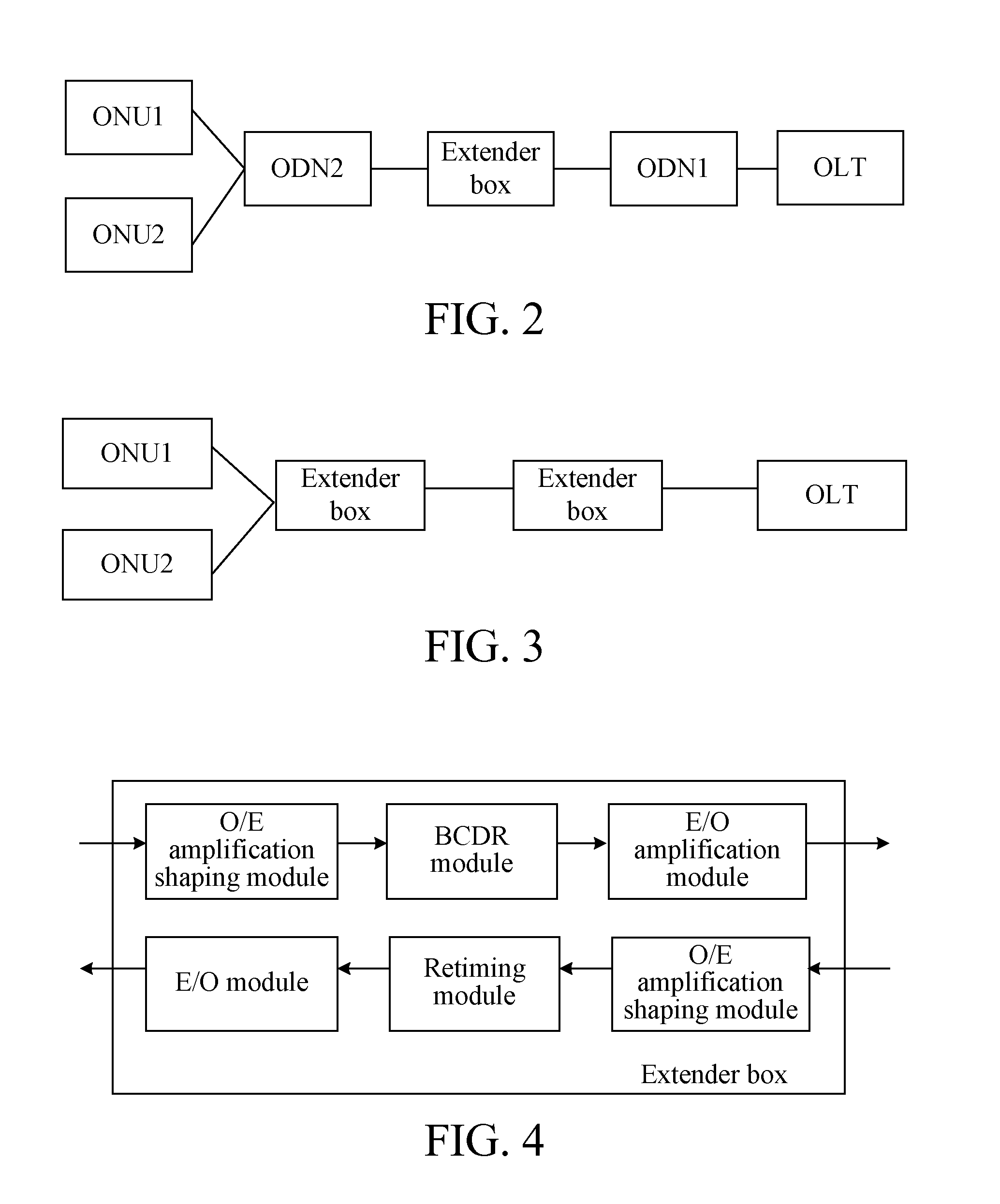
[0024]As seen from the above solutions, the method, the device, and the system provided in the embodiments of the present invention are applied in the data transmission extension system (the OEO equipment is included between the OLTs and the ONUs). As a preamble compensation function for a data frame is configured in the OEO equipment, the preamble impairment caused by the O / E conversion, amplification, and shaping performed on the data frame by the O / E amplification module and the BCDR performed on the data frame by the BCDR module in the OEO equipment can be compensated, thereby preventing that the subsequent receiver cannot correctly receive the data frame due to the preamble impairment of the data frame. Therefore, the present invention realizes the data transmission extension in an OEO manner.

Problems solved by technology

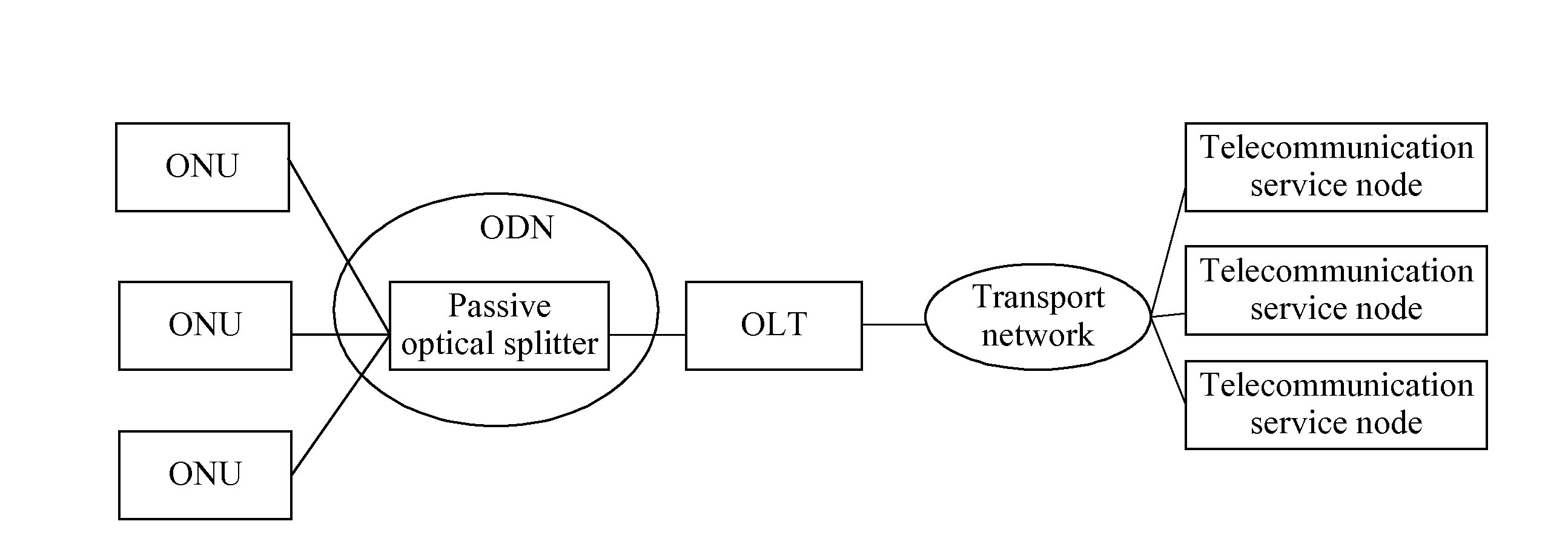
In the PON, as the number of ONUs interconnected to the OLTs through the passive optical splitter is relatively small, a cover radius is not longer than 20 kilometers, such that the number of OLTs is relatively large to fulfill the demands of the UE in the PON architecture, the location areas thereof are also remote and dispersed, which is inconvenient for management and maintenance, and has a high cost in establishment and maintenance of the PON.
Therefore, a power of the transmitted data does not gradually attenuate with the increasing of the transmission distance, such that the OLTs or ONUs receiving the data are unable to receive data.
However, the use of two OEO extender boxes is not economical.
However, this manner does not significantly improve the power budget.
However, during such processing, if it is ensured that each burst data frame after O / E conversion, amplification, and shaping is correctly received and the clock data can be recovered, a certain adjustment period is required, thereby resulting in preamble impairment of the data frame.
For subsequent OLTs that receive the data frame, the preamble of the data frame cannot satisfy the requirements on the byte number of the preamble specified in the protocol, such that the OLTs cannot correctly receive the data frame, and as a result, the OEO manner cannot actually realize data transmission extension.

Method used


Image

  • Method, system and device for realizing data transmission extension in passive optical network
  • Method, system and device for realizing data transmission extension in passive optical network
  • Method, system and device for realizing data transmission extension in passive optical network

Examples


Embodiment Construction

[0035]In order to make the objectives, technical solutions, and advantages of the present invention more comprehensible, the embodiments of the present invention are further described in detail in the following with reference to the accompanying drawings.

[0036]In order to realize the data transmission extension in an OEO manner, a problem that a subsequent receiver cannot correctly receive a data frame due to the preamble impairment of the data frame transmitted in an upstream direction caused by the OEO equipment has to be solved. Therefore, in the embodiments of the present invention, the OEO equipment is reconstructed. The equipment is not only able to perform E / O conversion, burst reception, power amplification, and O / E conversion on a data frame transmitted in an upstream direction, but also able to compensate the preamble impairment of the data frame caused by burst reception.

[0037]In the embodiments of the present invention, the reconstructed OEO equipment is referred to as 3...


PUM


Abstract

A method, a device, and a system for realizing data transmission extension in a passive optical network (PON) are provided. Between a burst-mode clock and data recovery (BCDR) module and an electrical-optical (E / O) amplification module, the device includes a delimiter matching module and a preamble buffering and compensating module. The delimiter matching module is adapted to receive a data frame sent by the BCDR module and determine a location of a delimiter in the data frame. An optical-electrical (O / E) amplification module performs O / E conversion, amplification, and shaping on the data frame. The BCDR module then performs clock and data recovery processing on the data frame. The preamble buffering and compensating module is adapted to receive and buffer the data frame output from the delimiter matching module, insert a compensation preamble in the data frame according to the location of the delimiter in the data frame determined by the delimiter matching module, and send the data frame to the E / O amplification module according to a retiming clock of a downstream direction. Therefore, the data transmission extension is realized in an optical-electrical-optical (OEO) manner.

Description

CROSS-REFERENCE TO RELATED APPLICATIONS[0001]This application is a continuation of International Application No. PCT / CN2008 / 071880, filed on Aug. 5, 2008, which claims priority to Chinese Patent Application No. 200710140504.3, filed on Aug. 10, 2007, both of which are hereby incorporated by reference in their entireties.FIELD OF THE TECHNOLOGY[0002]The present invention relates to the data transmission technology in a passive optical network (PON), and more particularly to a method, a system, and a device for realizing data transmission extension in the PON.BACKGROUND OF THE INVENTION[0003]As new services such as video on demand, high-resolution television, and online games have been gradually proposed, the users' demand for bandwidth increases day by day. The development of fiber-to-the-home technology effectively ensures the bandwidth of “last mileaccess network. A passive optical network (PON) technology is currently one of the most widely applied fiber-to-the-home technologies...

Claims


Application Information

Patent Timeline
IPC IPC(8): H04J14/02H04B10/29
CPCH04J3/1694H04L7/041
Inventor CHEN, JUANZOU, SHIMINZHOU, JIANLIN
Owner HUAWEI TECH CO LTD
Learn More