Scroll compressor

a compressor and scroll technology, applied in the direction of machines/engines, rotary/oscillating piston pump components, liquid fuel engines, etc., can solve the problems of deterioration of reliability, increase of sliding loss, and rise of pressure in the compression chamber, so as to maintain the pressure in the back pressure chamber stably, the effect of high performance and reliability

Inactive Publication Date: 2010-05-06
HITACHI APPLIANCES INC
View PDF2 Cites 53 Cited by
  • Summary
  • Abstract
  • Description
  • Claims
  • Application Information

AI Technical Summary

Benefits of technology

[0016]According to the invention, since the back pressure hole and the release flow path are arranged to prevent both of the fluidal communication and the another fluidal communication from being formed simultaneously during an orbital motion of the orbiting scroll, the p...

Problems solved by technology

That is, while the release valve is not in operation, leakage from the discharge space to the compression chamber occurs in the gap between the valve seat and the valve body, and this leakage causes the pressure of the compression chamber to rise.
This also increases a pressure variation of the back pressure chamber and when the leakage from the release valve is extremely large, the pressure of the back pressure chamber becomes excessively large, leading to an increase of sliding loss and deterioration of reliability due to seizing of the end plate.
Furthermore, when the release valve is in operation, tha...

Method used


Image

  • Scroll compressor
  • Scroll compressor
  • Scroll compressor

Examples


embodiment 1

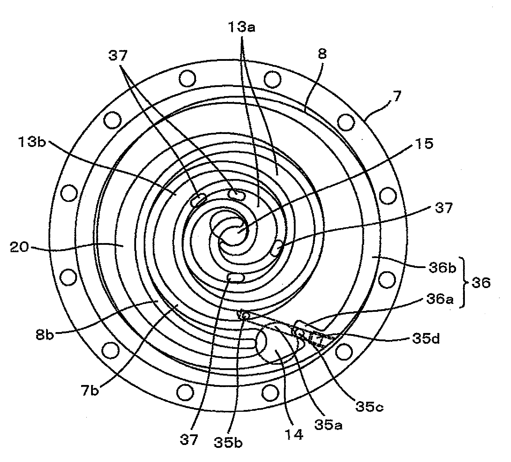
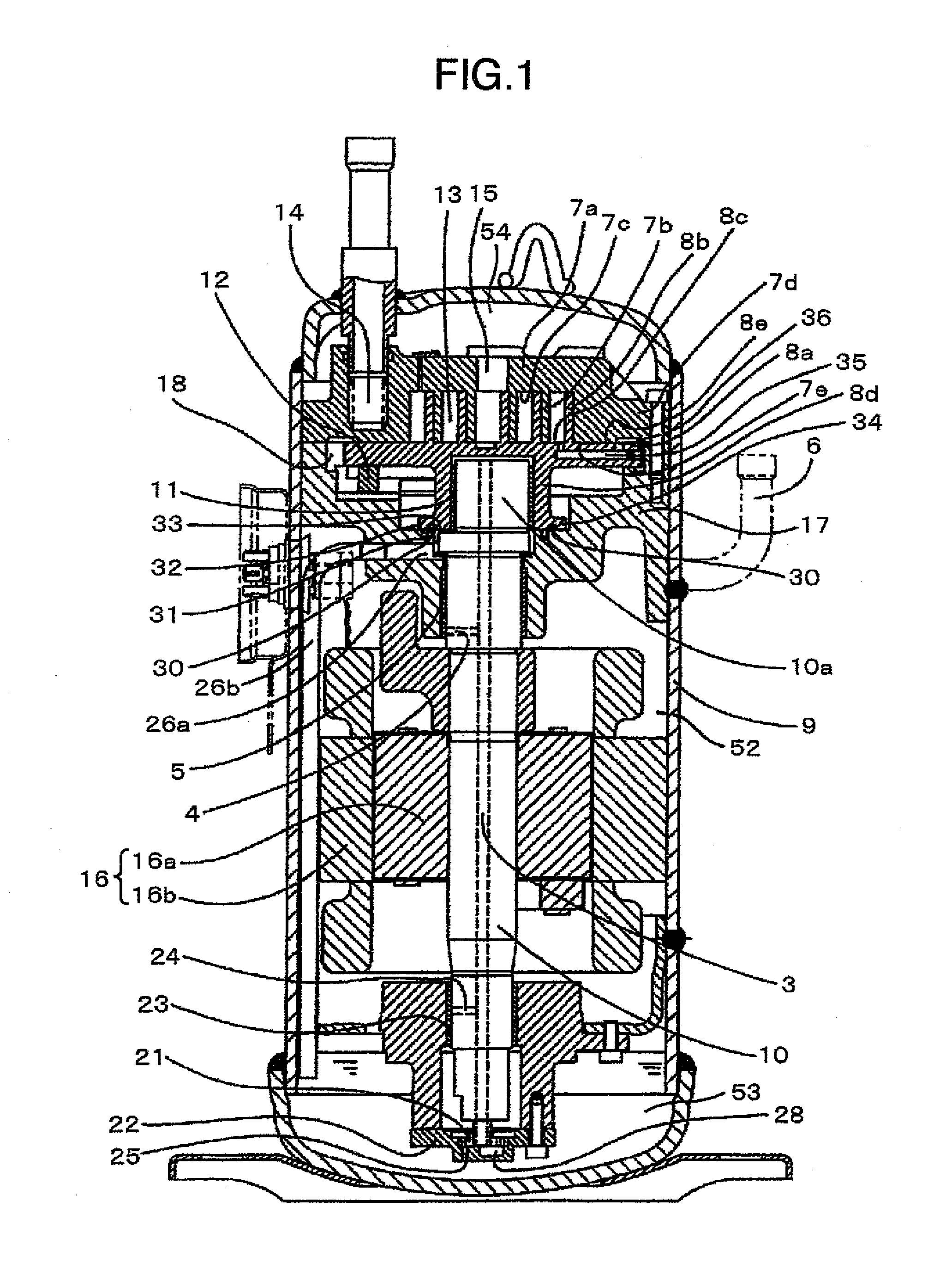
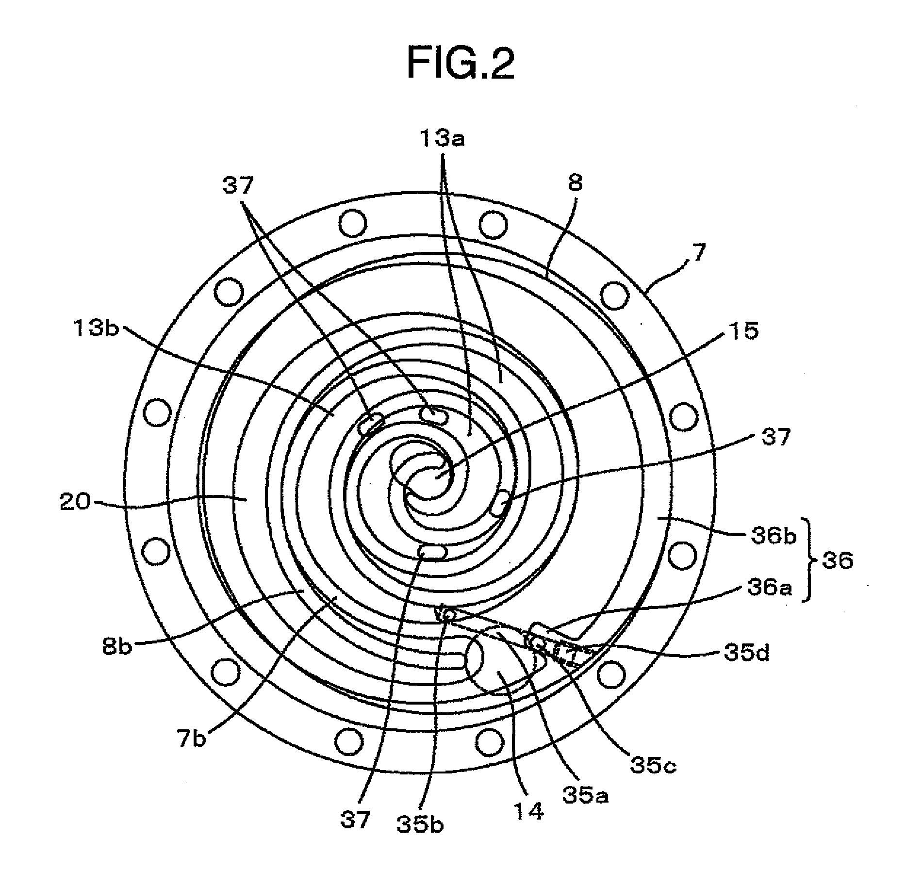
[0025]FIG. 1 is a longitudinal cross-sectional view of an entire scroll compressor illustrating Embodiment 1 of the present invention and FIG. 3 is an enlarged cross-sectional view of main parts showing an enlarged view of a scroll section made up of the fixed scroll member and the orbiting scroll member shown in FIG. 1.

[0026]As shown in FIG. 1 and FIG. 3, a fixed scroll (fixed scroll member) 7 includes a disk-shaped base plate 7a, a wrap 7b set upright in a spiral shape on the base plate 7a and a cylindrical support section 7d located on the outer peripheral side of the base plate 7a, that has an end plate surface contiguous to a distal end face of the wrap 7b and surrounds the wrap 7b.

[0027]The surface of the base plate 7a on which the wrap 7b is set upright is called a “tooth bottom 7c” because of its location between the wraps 7b.

[0028]Furthermore, the surface on which the support section 7d contacts an end plate 8a of a orbiting scroll (orbiting scroll member) 8 constitutes a...


PUM


Abstract

A scroll compressor comprises a fixed scroll, an orbiting scroll engaged with the fixed scroll to form a compression chamber therebetween, a back pressure chamber arranged at a back side of an end plate of the orbiting scroll, a back pressure hole formed in the end plate of the orbiting scroll to form a fluidal communication between the compression chamber and the back pressure chamber, and a release valve mechanism for discharging the fluid from the compression chamber to the discharge space when a pressure in the compression chamber is higher than the pressure in the discharge space, wherein the back pressure hole and the release flow path are arranged to prevent both of the fluidal communication and the another fluidal communication from being formed simultaneously.

Description

BACKGROUND OF THE INVENTION[0001]The present invention relates to a scroll compressor including a back pressure chamber on a back side of an orbiting scroll or a fixed scroll to press one of the scrolls against the other one of the scrolls with a back pressure.[0002]The scroll compressor has the fixed scroll with a spiral wrap set upright on a base plate and the orbiting scroll with a spiral wrap set upright on an end plate. The scroll compressor compresses a fluid (e.g., a gas coolant in a refrigeration cycle) by arranging the wraps of both of the scrolls to be engaged with each other and opposed to each other, and making the orbiting scroll orbit to reduce volumes of a plurality of compression chambers formed between the wraps.[0003]This compression operation produces a force in an axial direction for separating the fixed scroll and the orbiting scroll from each other. When the scrolls are separated from each other, a gap is produced between tooth tip and bottom of the respective ...

Claims


Application Information

Patent Timeline
IPC IPC(8): F04C18/02
CPCF04C18/0253F04C18/0261F04C23/008F04C27/005F04C29/128
Inventor CHIKANO, MASATSUGUTOJO, KENJIMATSUNAGA, MUTSUNORINAKAMURA, SATOSHI
Owner HITACHI APPLIANCES INC
Why Eureka
Try Eureka