Coupled Antenna Impedance Spectroscopy

a technology of impedance spectroscopy and coupled antennas, which is applied in the field of molecular spectroscopy of matter, can solve the problems of loss of signal to noise ratio and affect the commercial viability of methods

Inactive Publication Date: 2010-05-06
PHYSICAL LOGIC
View PDF0 Cites 11 Cited by
  • Summary
  • Abstract
  • Description
  • Claims
  • Application Information

AI Technical Summary

Benefits of technology

The technical effect of this patent is to allow for better measuring of glucose levels in deep tissues where they are most important for cells. This provides a way to get closer to the actual level of glucose available for use by cells.

Problems solved by technology

The technical problem addressed by this patent is how to develop a method for measuring glucose levels in living tissue through molecular spectroscopy without physically removing any part of the sample (known as non-invasive). Prior methods had limitations due to issues like electrode polarization, but this new approach overcomes those challenges to offer a better way to monitor glucose levels in real-time within deeper layers of tissue.

Method used


Image

  • Coupled Antenna Impedance Spectroscopy
  • Coupled Antenna Impedance Spectroscopy
  • Coupled Antenna Impedance Spectroscopy

Examples


Embodiment Construction

[0043]Referring to FIGS. 1 through 20, wherein like reference numerals refer to like components in the various views, there is illustrated therein a new and improved device and method of Coupled Antenna Impedance Spectroscopy.

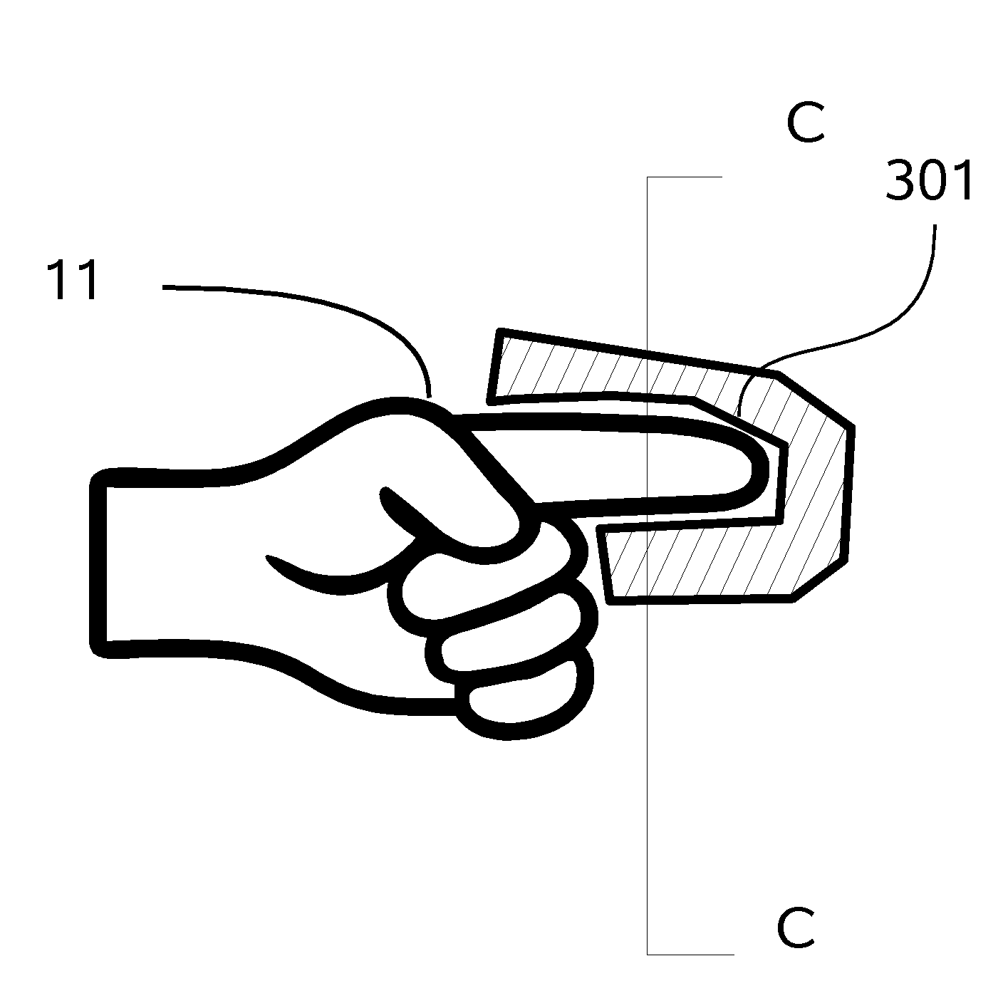
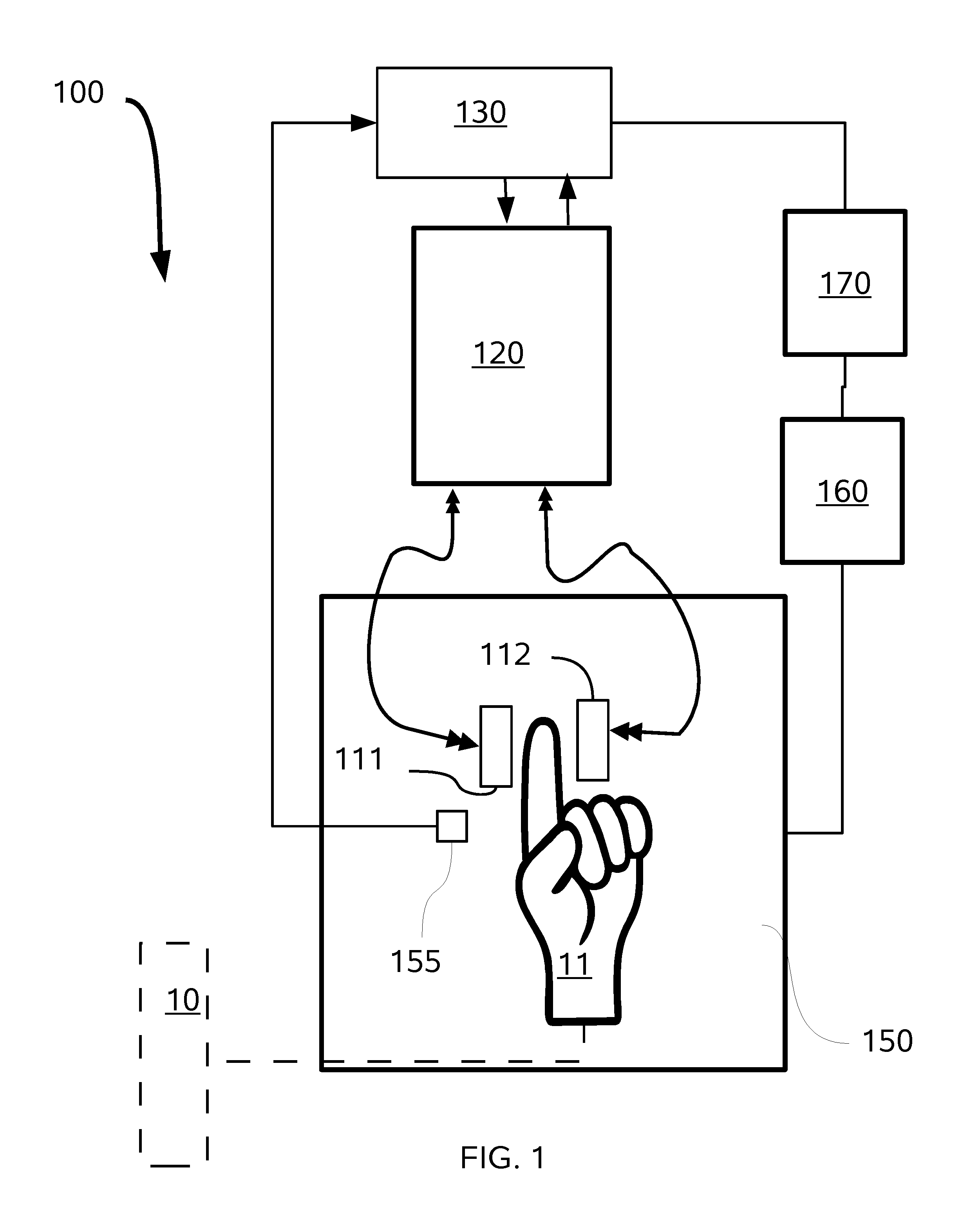
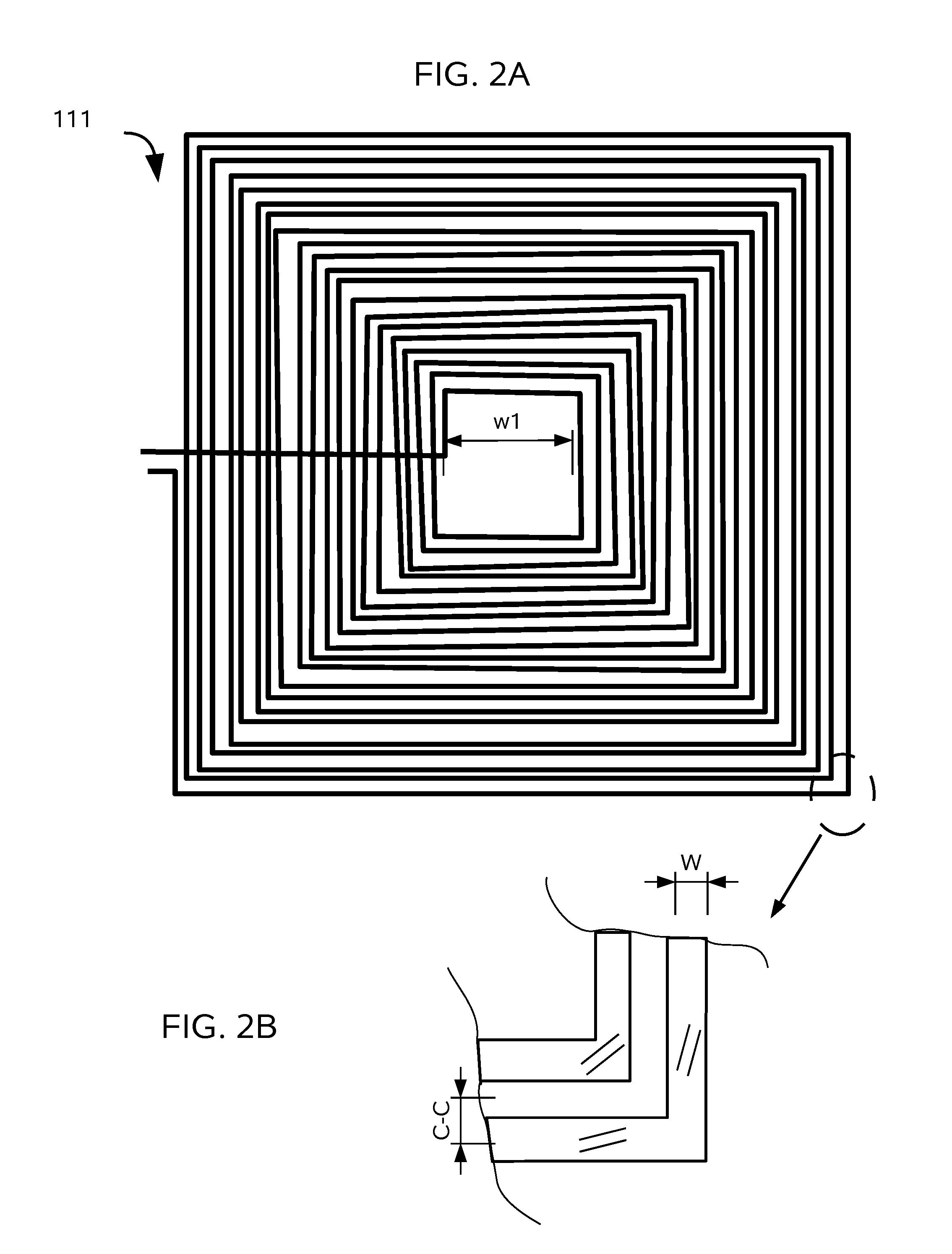
[0044]One embodiment of the inventive apparatus 100 for Coupled Antenna Impedance Spectroscopy is shown in FIG. 1 and can be deployed for either in vivo detection or in vitro samples. Apparatus 100 deploys a pair of coiled or patch antennas 111 and 112 on opposing sides of a test tube 10 (for in vitro measurement) or a limb 11, such as a finger, for in vivo measurements. It should be appreciated that in place of a test tube, a continuously flowing dielectric media can be sampled, such as a pipe in a process stream. The antennas 111 and 112 are energized via a vector network analyzer (VNA) 120. The vector network analyzer 120 is in signal communication with a general purpose computer 130 or microprocessor to perform calculations and calibration processes describ...


PUM


Abstract

It has been found advantageous to deploy coiled antennas as transmitters and receivers for acquiring the dielectric spectrum of materials. This method of impendence spectroscopy has been used to determine the concentration of glucose and other small polar molecules in vitro, as well as in vivo by placement on the antennas so that transmission is through the tissue, as for example on opposite sides of an organ or body part. The optimum selection of antenna coils permits deeper penetration into tissue for glucose detection, improves the SNR as well as expands the spectral range for greater accuracy and precision, to enable continuous non-invasive monitoring for either improved patient or automated management of diabetes.

Description


Claims


Application Information

Patent Timeline
Owner PHYSICAL LOGIC
Why Eureka
Try Eureka