
Subsurface measurement apparatus, system, and process for improved well drilling, control, and production

a measurement apparatus and subsurface technology, applied in the field of well drilling and completion, can solve the problems of large discrepancies between measured and calculated pressures, poor application of hydraulic models, and high effective mud weight that has the potential to fracture the formation

Inactive Publication Date: 2001-10-02
HALLIBURTON ENERGY SERVICES INC
View PDF24 Cites 29 Cited by
  • Summary
  • Abstract
  • Description
  • Claims
  • Application Information

AI Technical Summary

Benefits of technology

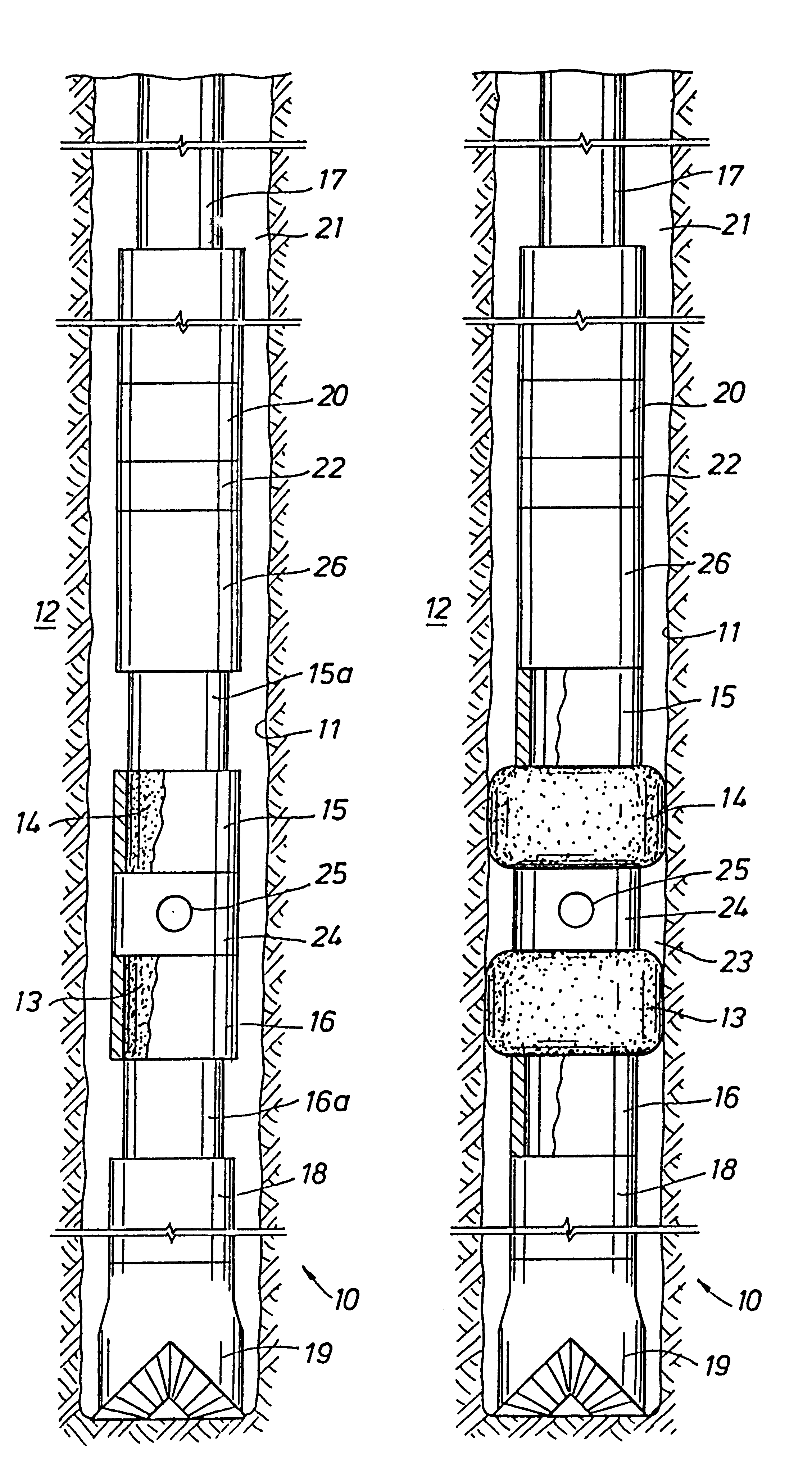
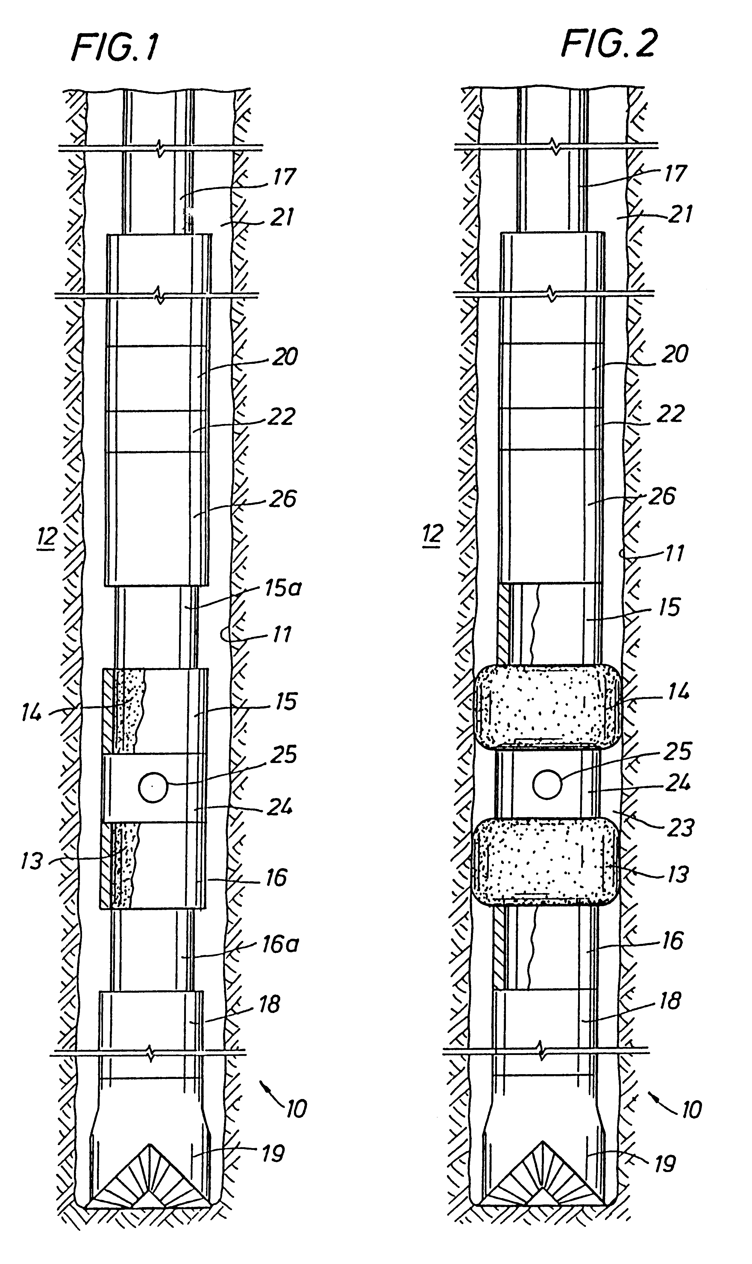
The present invention also employs a method of directly measuring subsurface well conditions in an area of the wellbore that is temporarily freed from the effects of circulating well fluids to obtain true subsurface condition values. Where the area being measured is isolated from the circulating fluid by an isolation packer during "pumps on," the measured data may be transmitted real time through the circulating fluid using FPT. In another method of the invention, measurements are made in an isolated part of the wellbore, the measurements are recorded, contact with the circulating well fluid is reestablished, and the recorded data is transmitted to the well surface using FPT. In either application, conventional FPT systems may be employed in a pumps off condition and / or in combination with an isolating well packer and subsurface recorder and measuring devices to obtain direct measurement of subsurface well parameters free of the effects of the well fluid used in the well's circulation system.
From the foregoing, it will be appreciated that a primary object of the present invention is to measure and record subsurface well conditions within an area of the wellbore, free from the effects of fluid circulating in the circulation system of the well, and transmit the recorded data to the well surface using FPT for directly evaluating one or more subsurface conditions without having to correct for the effects of the circulating well fluids.

Problems solved by technology

There are, however, often large discrepancies between the measured and calculated pressures due to uncertainties in the calculations through poor knowledge of pressure losses through certain components of the circulation system, changes in the mud density and rheology with temperature and pressure, and / or poor application of hydraulics models for different mud systems.
A surge pressure results from this movement, producing a higher effective mud weight that has the potential to fracture the formation.
Formation susceptibility to wellbore instability, although not problematic while drilling, may increase due to the swab and surge pressures incurred during tripping when the entire pipe string is rapidly withdrawn or reinserted in the well.
Modeling swab and surge pressure is difficult because of the manner in which the fluid flows as the pipe is moved within the well.
A pressure surge caused by breaking the gels when increasing the flow rate too quickly after breaking circulation has been responsible for many packoff and lost circulation incidents.
In this situation, where the well circulation is terminated for a period of time ("pumps off") and then reinitiated ("pumps on"), if the circulation rate is reinitiated too quickly, a pressure surge is created in the mud, causing a damaging imbalance with the formation.
This danger, which is particularly evident in high angle wells, led to the procedure of slowly bringing the volume of the mud pumps up anytime after circulation is temporarily suspended.
A pressure surge associated with restarting circulation may also be caused by a restriction in the annulus due to cuttings sagging and accumulating while the mud is static.
In extended reach and horizontal wells, hole cleaning can become critical.
If parts of the wellbore are unstable, as in common in these types of wells, the accumulation of cuttings, beds, and an overloaded annulus make it difficult to clean the hole properly.
These procedures, however, consume valuable time and may also damage the formation leading to further wellbore instabilities.
This process can be time-consuming, and the calculated results are subject to the correctness of the information and assumptions used for the values of the variable conditions affecting the mud column density.
If not controlled, the kick can reduce the density of the drilling fluid sufficiently to allow the formation pressure to flow uncontrollably through the well and become a "blowout."
Since the formation fluid type is generally unknown, it is not possible to determine the formation pressure from the casing shut-in pressure.
In high angle wells, a heavy cuttings load may increase the annular mud weight significantly.
These devices, however, are not suitable for use in all applications and also require highly specialized transmitting and receiving systems that are not as commonly available as arc the FPT systems.
Thus, real-time pressure and temperature information can only be sent real time while circulating the mud system.
However, sending all data may take an unacceptable amount of time.

Method used


Image

  • Subsurface measurement apparatus, system, and process for improved well drilling, control, and production
  • Subsurface measurement apparatus, system, and process for improved well drilling, control, and production

Examples


Embodiment Construction

Enhanced Leak-off Test (LOT) and Pressure Integrity Test (PIT) and Formation Integrity Test (FIT) Using Direct Pressure Measurement

In a typical LOT, the start of each well section, after casing and cementing the wellbore, a short interval (approximately 3 m) of new hole is drilled below the casing shoe. The well is then shut in and the wellbore pressured up by pumping at a slow rate until the wellbore strength is exceeded and mud starts to leak off (LOT) or until a specified pressure is achieved (PIT / FIT). These pressures are monitored from the well surface. This test is used to verify the casing cement integrity, the kick tolerance for the next section, and an estimate of the openhole fracture strength.

Because of the small margins between pore or collapse pressure and fracture pressure in many HPHT, deepwater, and extended reach / horizontal wells, the LOT has become a critical measure of the formation strength and is used as a guide to the maximum allowable circulating pressure in t...


PUM


Abstract

Subsurface wellbore conditions are measured directly in the wellbore while the fluid circulation system is not pumping. The measured values are recorded at the subsurface location and subsequently transmitted to the well surface when circulation is resumed using fluid pulse telemetry (FPT). Real-time measurements made / when the fluids are circulating are transmitted real time using FPT. Axially spaced measurements are used to obtain differential values. The apparatus of the invention comprises an assembly carried by a drill string that is used to selectively isolate the area within the well that is to be evaluated. The apparatus includes an assembly having axially spaced inflatable well packers that are used to isolate an uncased section of the wellbore. The apparatus is equipped with self-contained measuring and recording equipment, a fluid receiving reservoir, circulation valving, measurement while drilling equipment, and automated controls. Measurements are made while the circulation is terminated or while the well packers are being used to isolate an area of the wellbore from the circulating fluid. The method is used to directly measure and evaluate conditions caused by pumping and drill string movement, such as swab and surge pressures. Other conditions such as the formation strength, formation pressure, the fluid density, and other subsurface conditions related to the well are also measured.

Description

1. Field of the InventionThe present invention relates to the field of well drilling and completion. More specifically, the present invention relates to direct measurement apparatus and methods for evaluating subsurface conditions in a wellbore.2. Description of the Background ArtIn a typical well drilling operation, conditions in the wellbore must be closely monitored and controlled to optimize the well operation and to maintain control of the well. One of the most important conditions in well drilling procedures is the bottomhole pressure of the circulating drilling fluid or "mud" used in forming or conditioning the well. The actual or effective density of the mud is an important condition that can be affected by a number of different variables related to the composition of the mud, the characteristics of the formation being penetrated by the wellbore, the dynamics of the drilling mechanism, and the procedures being implemented in the wellbore. In this latter regard, for example, ...

Claims


Application Information

Patent Timeline
Patent Type & Authority Patents(United States)
IPC IPC(8): E21B47/18E21B47/12E21B47/06E21B21/08E21B33/124E21B43/26E21B49/00E21B49/08
CPCE21B21/08E21B33/1243E21B43/26E21B47/06E21B47/124E21B47/18E21B49/006E21B49/008E21B49/08E21B49/087E21B47/26
Inventor WARD, CHRISTOPHER D.
Owner HALLIBURTON ENERGY SERVICES INC
Learn More