
Packaging equipment and process for controlling of the packaging equipment

a technology of packaging equipment and packaging parts, which is applied in the field of packaging equipment, can solve the problems of product safety hazards for the final consumer eating the product, metal parts are likewise hazardous, and the parts of metal tools used in comminuting the components of filling materials can be damaged and broken, so as to prevent any major loss of filling materials

Active Publication Date: 2010-05-06
POLY CLIP SYST
View PDF4 Cites 5 Cited by
  • Summary
  • Abstract
  • Description
  • Claims
  • Application Information

AI Technical Summary

Benefits of technology

[0017]The object of the present invention is therefore to design a packaging device of the kind initially specified in such a way that a metallic impurity is reliably detected, while preventing any major loss of filling material and extended periods in which operation of the device is discontinued.
[0021]Depending on the detection signal being outputted from the sensor unit, a signal can thus be supplied to the clipping unit such that the clipping unit adopts a predetermined operating mode with a correspondingly defined operating behavior. The special operating mode of the clipping unit, which is set by the control unit depending on detection of the impurity, serves to designate a specific amount of product in a special manner such that said amount of product differs reliably in its arrangement and appearance from the product resulting from normal troublefree operation. The product modified by the changed operating behavior resulting from actuation by the control unit can be identified as the product in which the impurity is definitely located, so the contaminated region of the filling material is not ejected with substantial losses and production stoppages in the course of normal further processing of the product, and particularly during normal and troublefree product throughput, but instead is passed through the device in a predetermined, precisely defined manner. In this way, controlled, detection-based actuation of the clipping unit such that it enters a particular operating state or operating mode causes a change in the shape and arrangement of the product, with the result that a region of the product containing the metallic impurity can be distinguished with a very high level of probability from the uncontaminated products.
[0022]With the device according to the invention, it is therefore possible to detect a metallic impurity reliably, and, without interrupting the production process, i.e., the operation of the device as a whole, to mark a part of the product in such a way that the impurity can be unambiguously associated with this marked part of the product. There is no necessity to use other devices or methods in order to apply a special marking.

Problems solved by technology

When filling material 2 is being processed, and particularly during mixing and comminution of components of filling material 2, it is possible, for example, that parts of the metal tools for comminuting the components of filling material 2 can be damaged and break off.
If, during operation of the packaging device, filling material 2 is contaminated by such metal parts, then these metal parts may end up in the finished product (for example in a sausage), which means that the product may be hazardous for the final consumer eating the product.
Such metal parts are likewise hazardous in view of the fact that the product packaged in portions in casing 8, for example, is further processed in another processing operation.
In that case, apparatus and machinery provided for further processing may be damaged.
However, such handling is very laborious and time-consuming and leads to the undesirable and protracted stoppage of the device.
Manual intervention is also required, wherein disassembly and re-assembly of the device or at least parts thereof can be dangerous for the operating personnel.
Hence, in addition to the extended period that operation of the device is discontinued, substantial amounts of filling material 2 are also lost.

Method used


Image

  • Packaging equipment and process for controlling of the packaging equipment
  • Packaging equipment and process for controlling of the packaging equipment
  • Packaging equipment and process for controlling of the packaging equipment

Examples


Embodiment Construction

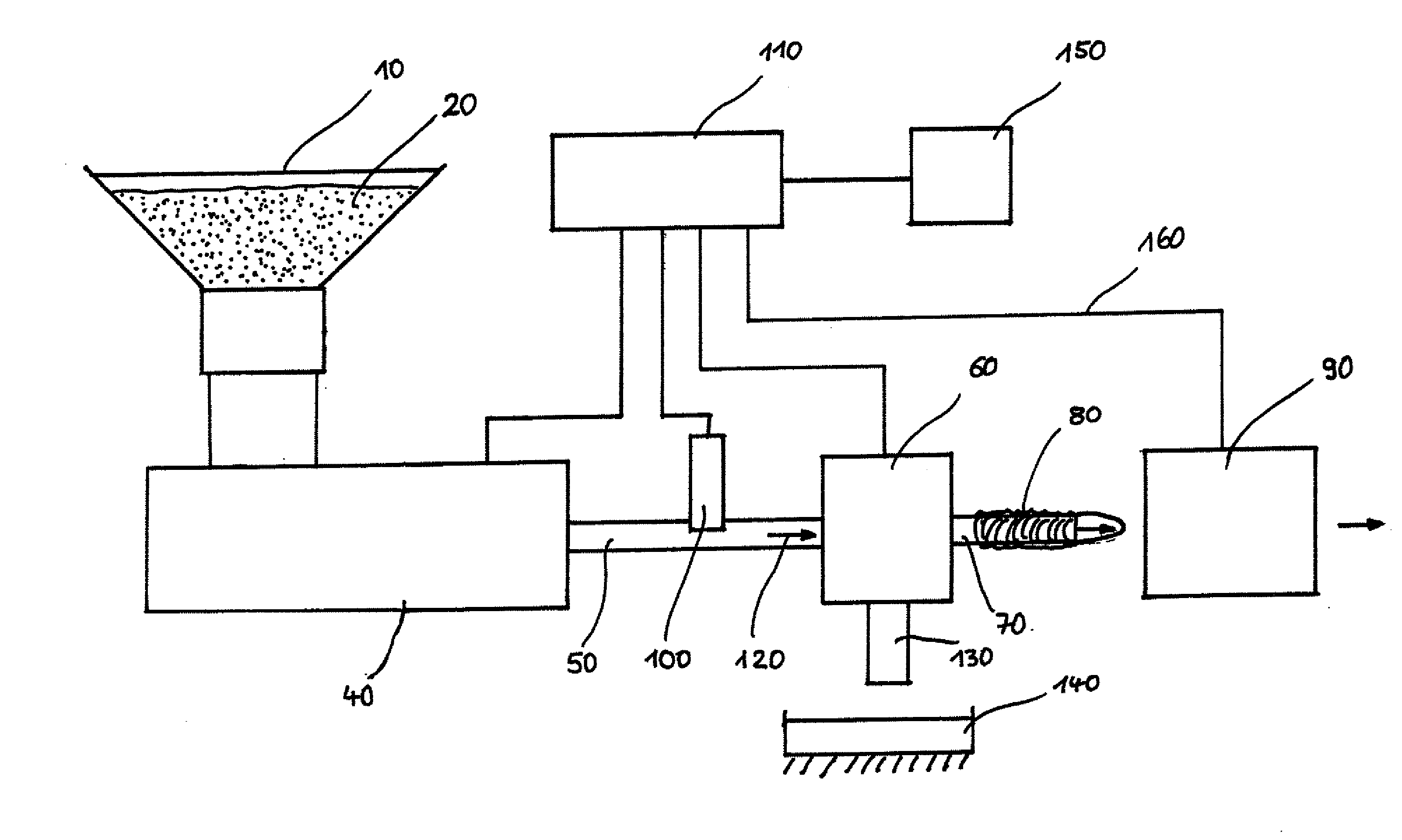
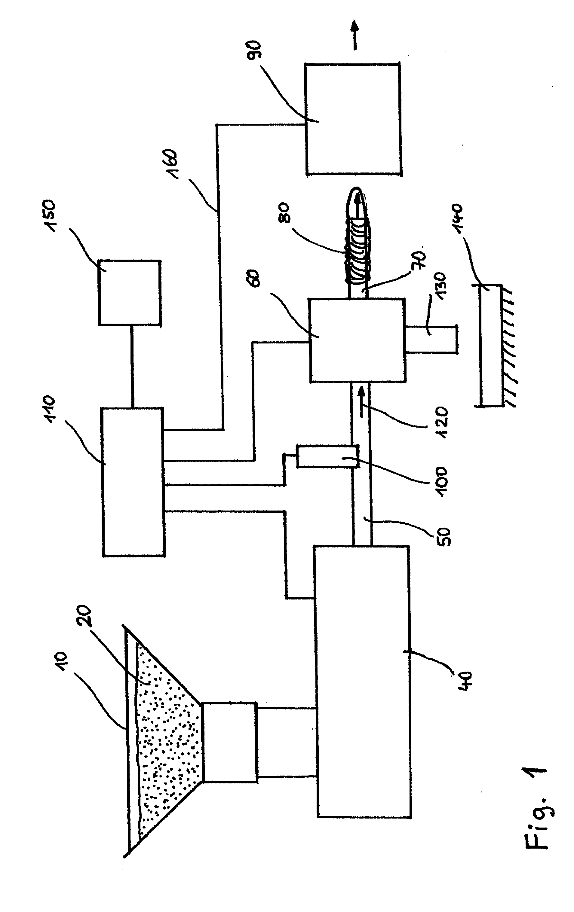
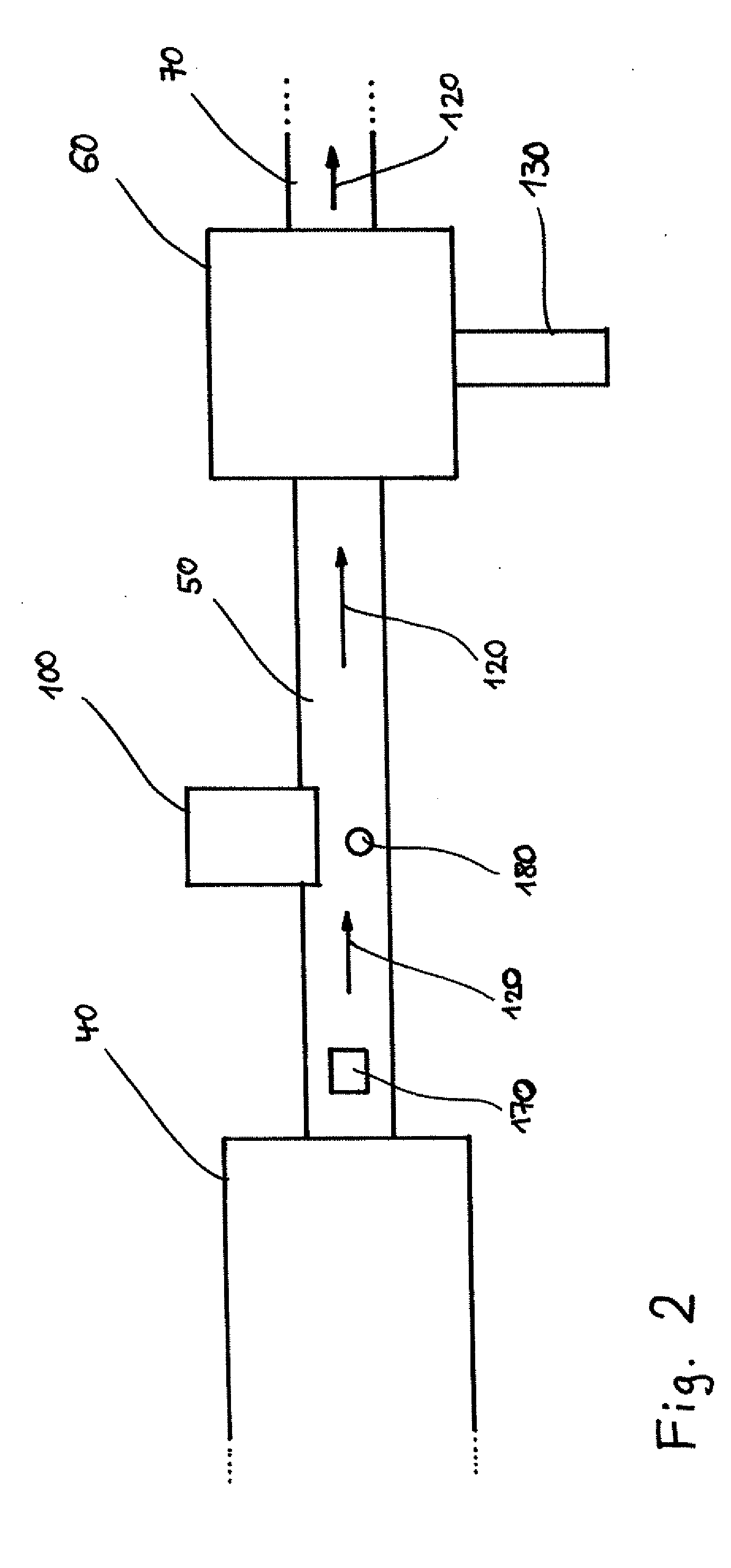
[0042]FIG. 1 shows a schematic view of the arrangement of a packaging device according to the present invention.

[0043]According to FIG. 1, a filling material 20 located in a container 10 is fed to a filling unit 40, which for its part generates, with a predetermined pressure, a volumetric flow that feeds filling material 20 to a valve unit 60 via a connecting pipe 50. By means of a filling pipe 70 disposed on valve unit 60, onto which filling pipe a predetermined amount of a casing 80 for packaging filling material 20 is arranged, the casing 80 closed on one side at a particular place is stuffed with filling material 20. Stuffed casing 80 is fed to a clipping unit 90 disposed in the direction of movement of stuffed casing 80, in which clipping unit the portioning is carried out by respective displacement devices in the manner described above with reference to FIG. 3, wherein a predetermined amount of the filling material 20 is disposed in casing 80 and is portioned by the displaceme...


PUM

PropertyMeasurementUnit
Flow rateaaaaaaaaaa
Sizeaaaaaaaaaa

Abstract

A packaging device including a filling unit for transporting a filling material, a filling tube connected to said filling unit, for introducing the filling material supplied by the filling unit into a tubular casing and for ejecting the filling material located in the casing, a clipping unit disposed in the direction of transport of the filling unit, for constricting the casing at a predetermined position and for closing the casing with at least one closure element, a sensor unit disposed between the filling unit and the filling tube, for detecting impurities in the filling material and for emitting a detection signal to a control unit, wherein the control unit has a control connection to the clipping unit. The invention also relates to a method for controlling a packaging device.

Description

BACKGROUND OF THE INVENTION[0001]The present invention relates to a packaging device, and in particular to a packaging device in which a filling material is introduced into a tubular casing, and to a method for controlling a packaging device.[0002]A packaging device known from practice, in which a filling material is introduced into a tubular casing, is shown in FIG. 3. Such a packaging device can be used to produce sausages, for example.[0003]The packaging device in FIG. 3 comprises a mostly funnel-shaped filling container or storage container for the liquid, pasty and / or granular filling material, which may, for example, be sausage meat for producing sausages. The filling material 2 is supplied to a filling unit 4. Filling unit 4, also referred to as a filler, causes filling material 2 to be ejected via a connecting pipe 5 to a valve unit 6. A filling tube 7, on which a tubular casing 8 closed at one end by means of a closure element is arranged, is connected to valve unit 6. Casi...

Claims


Application Information

Patent Timeline
IPC IPC(8): A22C11/02A22C11/12
CPCA22C11/0254A22C11/125B65B9/12B65B51/04B65B57/005
Inventor FREIBERGER, GERDSCHMALFELD, RALF
Owner POLY CLIP SYST
Learn More