Catheter with pressure sensor

a technology of pressure sensor and catheter, which is applied in the field of catheter with pressure sensor, can solve the problems of increasing the cost of use of such a product, unsuitable or undesirable for many diagnostic or treatment purposes, and the bladder typically must have a relatively long length

Inactive Publication Date: 2010-05-06
INNERSPACE
View PDF38 Cites 15 Cited by
  • Summary
  • Abstract
  • Description
  • Claims
  • Application Information

AI Technical Summary

Benefits of technology

[0011]In another preferred embodiment, the pressure sensor assembly can be covered by a sheath having a plurality of apertures or slits. This sheath provides physical protection to the balloon while allowing pressure from the patient's body to be communicated to the tube.

Problems solved by technology

However, the pressure sensing equipment on prior art pressure sensing catheters often make them unsuitable or undesirable for many diagnostic or treatment purposes.
Generally, these catheters are relatively expensive to manufacture due to the integrated transducer and therefore do not always achieve a price point suitable for disposable use.
Further, these catheters often require specialized and expensive equipment that connect to this catheter, which further increases the cost of use for such a product.
First, the bladder typically must have a relatively long length, which prevents much of the distal end of the catheter from being used for other purposes.
Second, these shrink bladders have a generally large diameter due to the size of the bladder and its furled configuration.
Hence, these catheters are not suitable for smaller diameter uses such as in arterial lines, PICC lines and central venous catheters.
Finally, these shrink bladders are often not suitable for uses that require that the catheter be forcibly pushed through skin and tissue as is the case in a central venous catheter as the bulk of the folded bladder increases the difficulty of insertion and the trauma to the tissue through which it passes.

Method used


Image

  • Catheter with pressure sensor
  • Catheter with pressure sensor
  • Catheter with pressure sensor

Examples


example 1

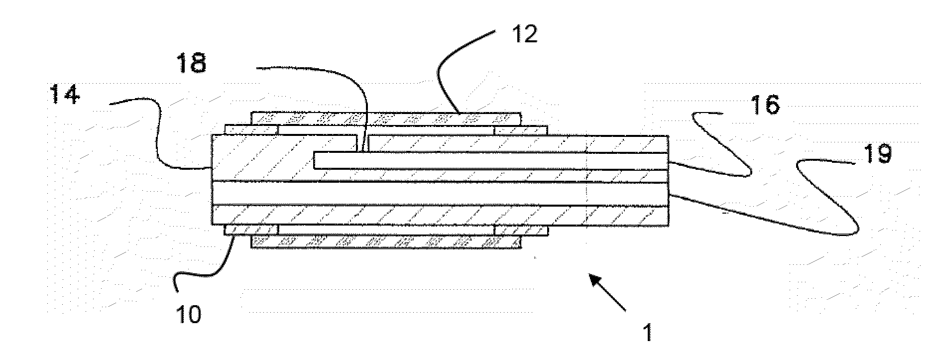
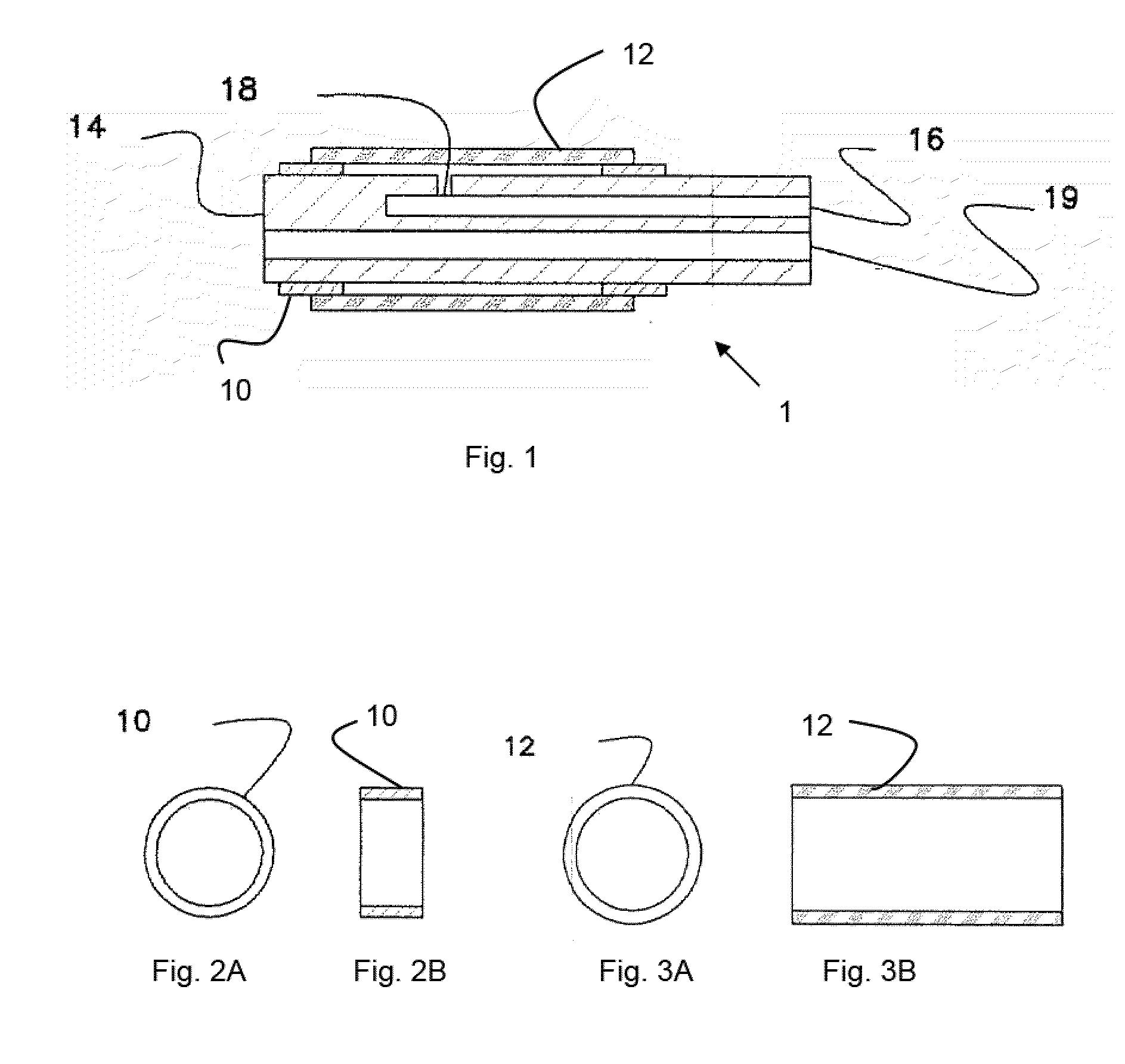
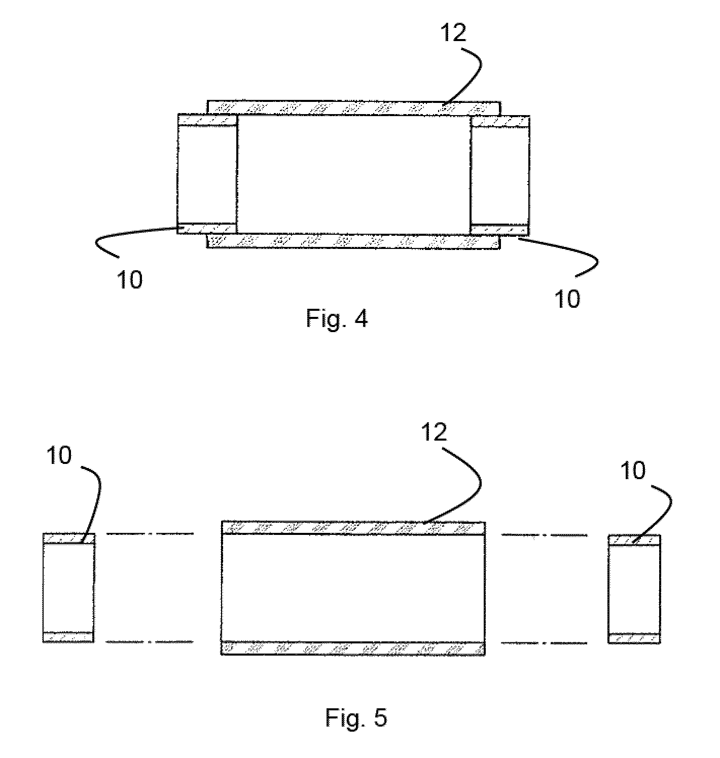
[0051]A variable volume sensor assembly suitable for use in a catheter is formed by placing a set of sleeves on either side of an aperture passing through a wall of the catheter and into an internal lumen that leads to an external pressure transducer. Each end of a flaccid tube is bonded to one of the sleeves, forming an annulus defined by the internal diameter of the sleeve and the outer diameter of the catheter body beneath the sleeve. The volume of the enclosed space can be determined by multiplying the area of the annulus times the distance between the sleeves.

[0052]During use, the flaccid tube changes shape in response to changes in pressure, which therefore changes the area of the annulus. This area change is analogous to the change in area that occurs when a circle is deformed to the shape of an ellipse. The circumference of the circle and the ellipse is the same, but the area is different. As the area of the tube changes, the area of the annulus that defines the volume of th...


PUM


Abstract

A pressure sensor assembly is disclosed which includes a flaccid tube having two mounting sleeve members that bond the tube to a distal end of a catheter. The catheter includes an aperture located beneath the tube and in communication with an air passage. As the pressure outside the tube changes, the tube moves relative to the catheter body, thereby communicating that pressure change to the sealed air passage within the catheter. This air passage is connected to an external transducer that can measure this pressure change and thereby determine a pressure at the distal end of the pressure catheter.

Description

RELATED APPLICATIONS[0001]This application claims priority to U.S. Provisional Application Ser. No. 61 / 197,039 filed Oct. 24, 2008 entitled A Single Lumen Catheter with Separate Tubes Therein and U.S. Provisional Application Ser. No. 61 / 197,041 filed Oct. 24, 2008 entitled A Catheter with an Integrated Pressure Sensor all of which are hereby incorporated herein by reference.BACKGROUND OF THE INVENTION[0002]During medical procedures, catheters are often inserted into various locations of a patient, such as vessels, ducts, and body cavities. During many catheter procedures, it can be valuable to sense the pressure within the patient, for example, to determine blood pressure or intracranial pressure. However, the pressure sensing equipment on prior art pressure sensing catheters often make them unsuitable or undesirable for many diagnostic or treatment purposes.[0003]For example, U.S. Pat. No. 4,722,348, the contents of which are hereby incorporated by reference, is directed to a cathe...

Claims


Application Information

Patent Timeline
Patent Type & Authority Applications(United States)
IPC IPC(8): A61B5/00A61B1/00
CPCA61M2025/0003A61M25/003A61M25/0032
Inventor BOBO, SR., DONALD E.
Owner INNERSPACE
Why Eureka
Try Eureka