Vehicle
a technology for vehicles and body parts, applied in the field of vehicles, to achieve the effect of reducing the angle of inclination of the vehicle body
- Summary
- Abstract
- Description
- Claims
- Application Information
AI Technical Summary
Benefits of technology
Problems solved by technology
Method used
Image
Examples
first embodiment
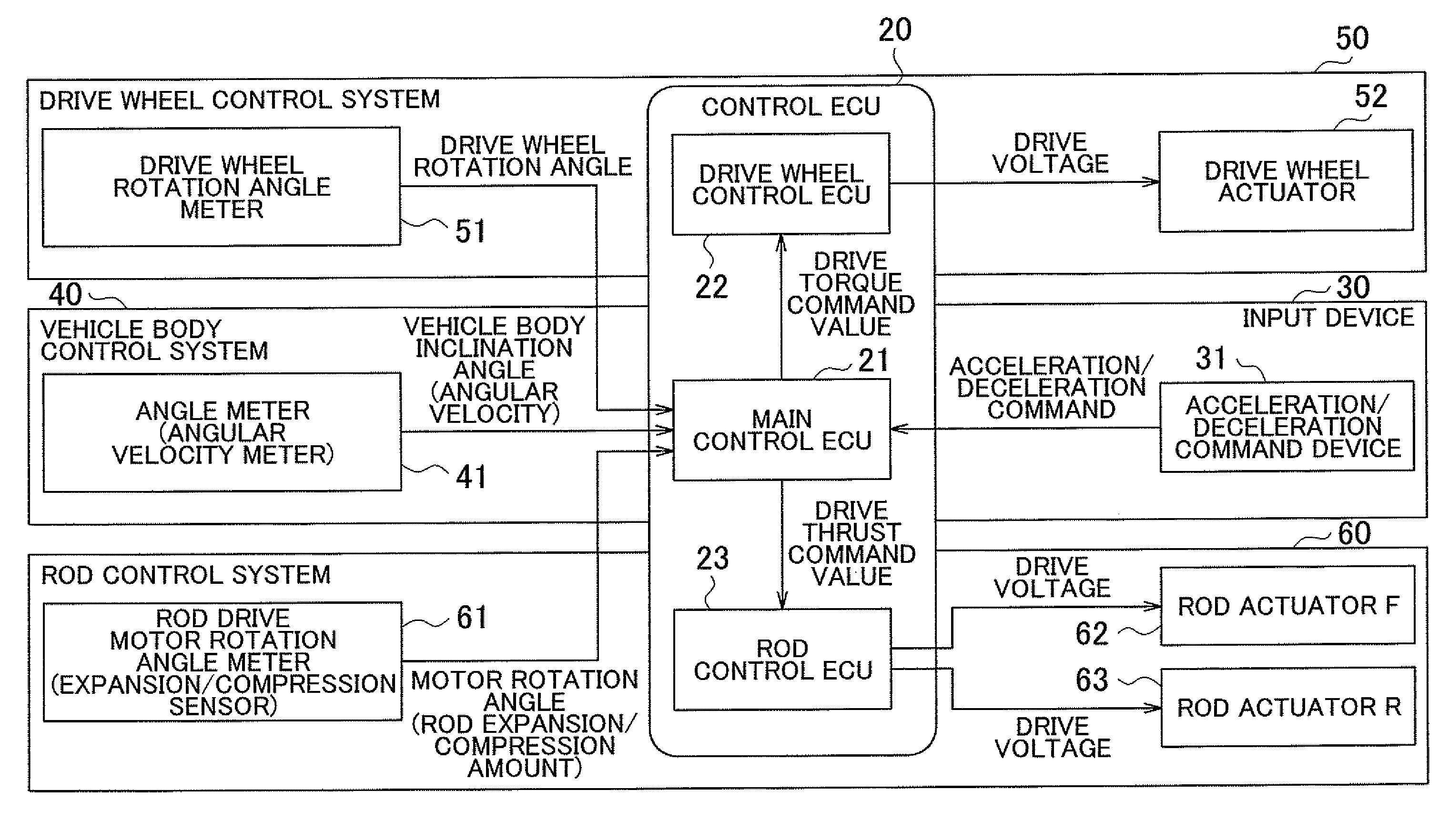
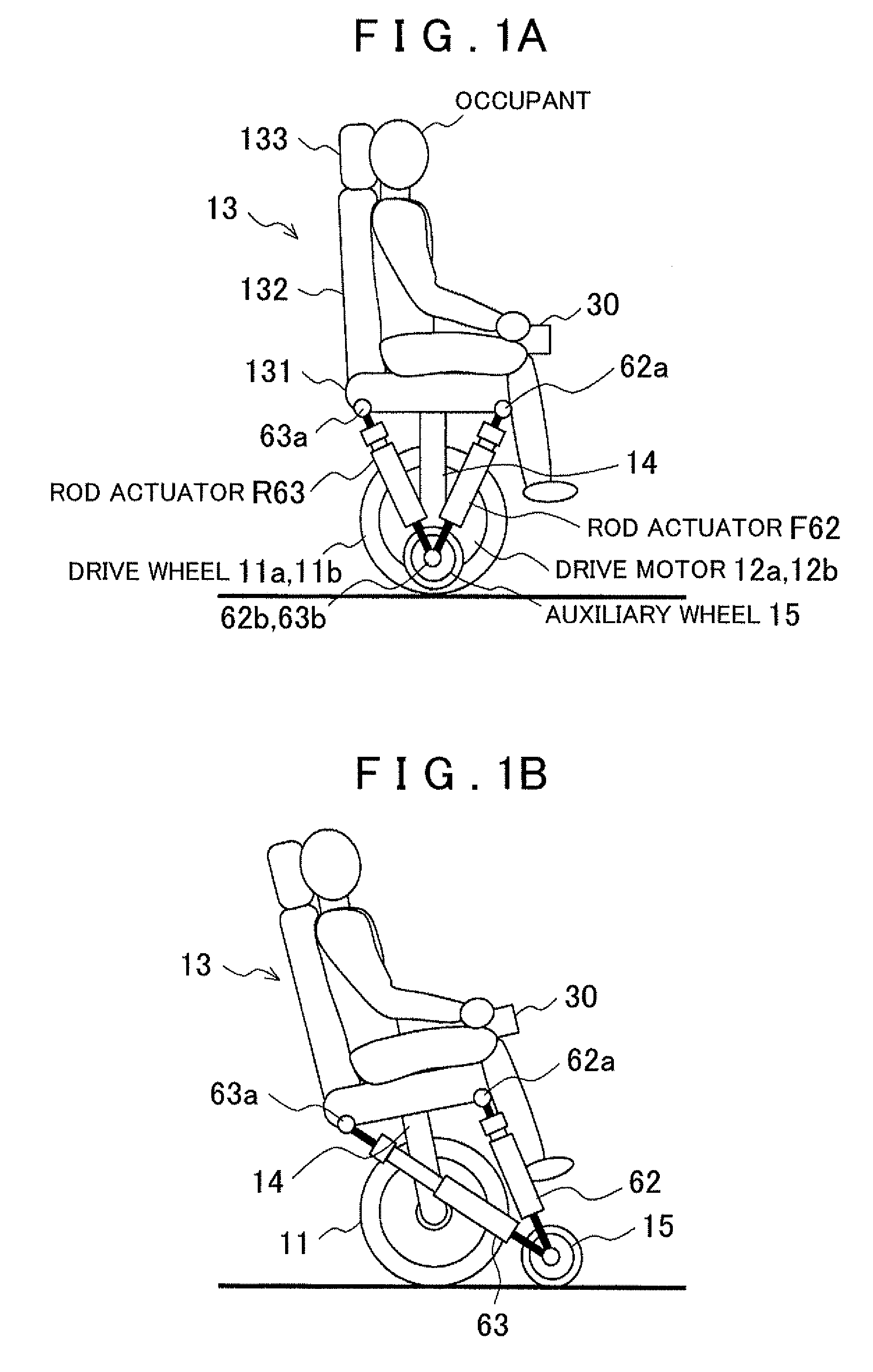
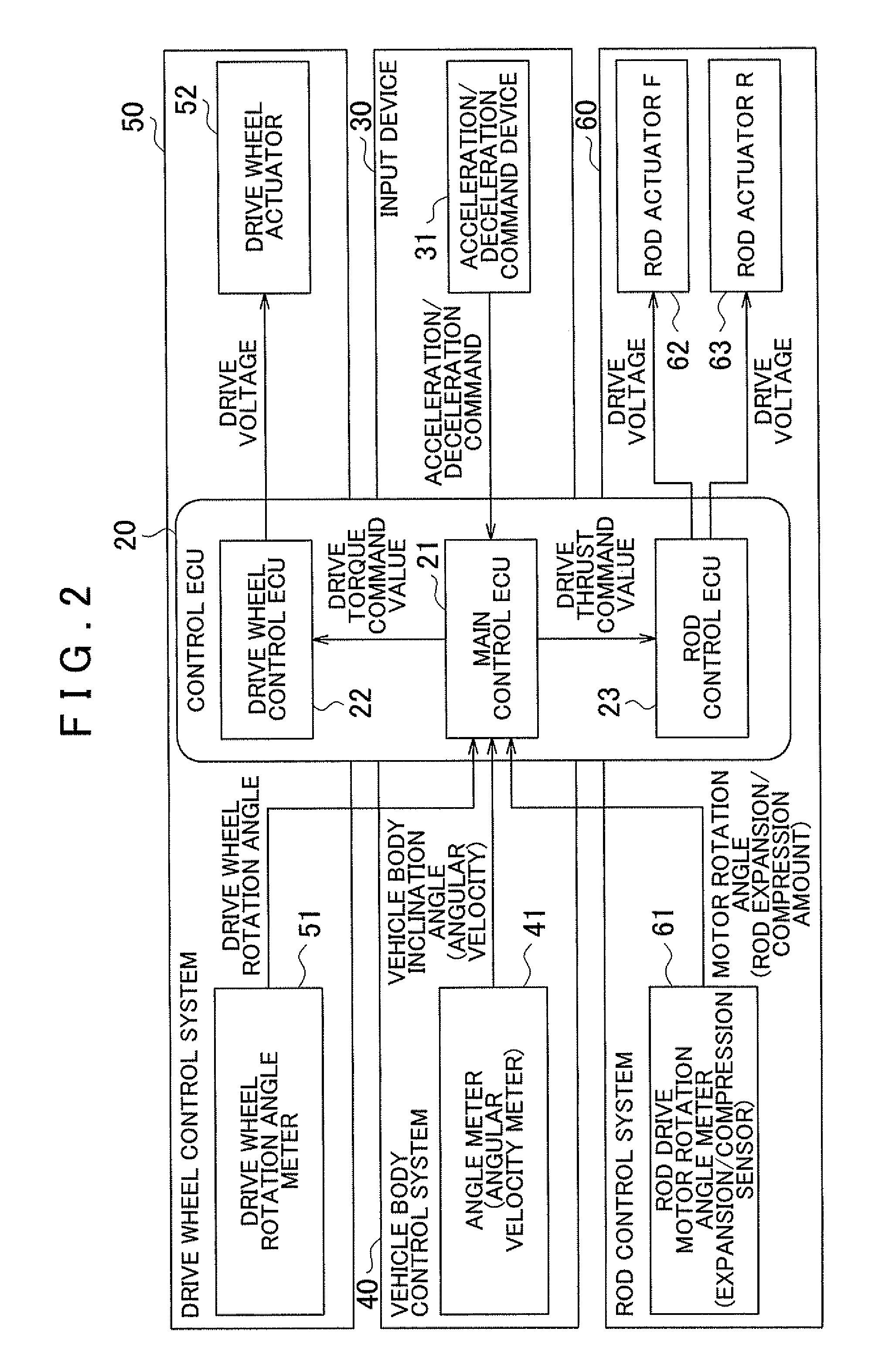
[0066]FIGS. 1A and 1B show examples of an external appearance with an occupant riding a vehicle according to a As shown in FIG. 1A, the vehicle includes two co-axially disposed drive wheels 11a (11b). Drive wheels 11a, 11b are driven respectively by drive motors 12a, 12b. A riding section 13 (seat) for mounting an occupant or cargo (weight bodies) is disposed on an upper section of the drive wheels 11a, 11b (hereafter, the drive wheels 11a, 11b will be collectively referred to as drive wheels 11. Other components will be treated the same below) and the drive motor 12. The riding section 13 is formed from a seat cushion 131 on which a driver sits, a seat back 132 and a head restraint 133. The riding section 13 is supported by a support member 14 fixed to a drive motor housing that houses the drive motor 12.
[0067]An input device 30 is disposed on the side of the riding section 13. The input device 30 is operated by a driver to perform vehicle commands such as acceleration, decelerati...
second embodiment
[0130]A second embodiment will be described below.
[0131]In the first embodiment, the maximum vehicle body angle of inclination θ1,Max determining the threshold αMax are fixed values determined in advance by a designer. In contrast, in the second embodiment, the differences in a permissible range of vehicle body inclination for occupants are taken into account and the occupant can select the maximum vehicle body angle of inclination θ1,Max. For example, control is performed to ensure balance to the greatest degree possible when the vehicle body is inclined by increasing the maximum vehicle body angle of inclination θ1,Max (threshold αMax). Conversely, for an occupant requiring running without inclination of the vehicle body, control is performed to maintain the posture to the greatest degree possible with the auxiliary wheels 15 by reducing the maximum vehicle body angle of inclination θ1,Max (threshold αMax). Thus an inverted pendulum vehicle is realized by limiting the vehicle body...
third embodiment
[0140]Next a third embodiment will be described.
[0141]As described with reference to the first embodiment, the auxiliary wheels 15 are displaced to a target position b* by feedback control. As a result, when a displacement lag is produced, since braking is applied before the auxiliary wheels 15 reach the target position b* for the auxiliary wheels, there is the possibility of temporary forward inclination of the vehicle body or drive wheel slip. Thus in the third embodiment, the target deceleration α* is limited until the auxiliary wheels 15 reach the target position b* with respect to “lags” in the displacement of the auxiliary wheels 15. More precisely, the target deceleration α* is limited by the actual auxiliary wheel position b. In this manner, loss of balance during deceleration due to vehicle body inclination and auxiliary wheel ground contact can be prevented and forward vehicle inclination and slip can be prevented. This serves as a failsafe if a system of displacing the au...
PUM
 Abstract
Description
Claims
Application Information
 - R&D
- Intellectual Property
- Life Sciences
- Materials
- Tech Scout
- Unparalleled Data Quality
- Higher Quality Content
- 60% Fewer Hallucinations
Browse by: Latest US Patents, China's latest patents, Technical Efficacy Thesaurus, Application Domain, Technology Topic, Popular Technical Reports.
© 2025 PatSnap. All rights reserved.Legal|Privacy policy|Modern Slavery Act Transparency Statement|Sitemap|About US| Contact US: help@patsnap.com


