Method for Controlling Vehicle Dynamics

a vehicle dynamics and control system technology, applied in the direction of steering initiation, instruments, vessel construction, etc., can solve the problems of inaccurate vehicle state variables, unadjusted response, and inability to respond appropriately, so as to improve accuracy and reliability

Inactive Publication Date: 2010-05-06
VOLKSWAGEN GROUP OF AMERICA
View PDF11 Cites 78 Cited by
  • Summary
  • Abstract
  • Description
  • Claims
  • Application Information

AI Technical Summary

Benefits of technology

[0012]It is accordingly an object of the invention to provide a method for controlling vehicle dynamics which improves accuracy and reliability of prior art methods and which can be implemented in a cost-efficient manner in production vehicles.

Problems solved by technology

If current values for the friction coefficient between the vehicle tires and the road surface and current values for the motion of the vehicle are not known or if current values defining the vehicle state are only crudely approximated, then vehicle dynamics control systems need to be tuned conservatively taking into account that the variables defining the vehicle state may be inaccurate.
As a result, vehicle dynamics control systems may engage too early and they may not respond appropriately in certain situations.
The lateral velocity is usually calculated by integrating acceleration values, which often results in inaccurate values for the lateral velocity of the vehicle.
Measuring rotation rates of the vehicle and lateral accelerations of the vehicle may therefore be insufficient for providing accurate lateral velocity estimates for all dynamic conditions.
Specific cases, in which the measurements performed by rotation rate sensors and lateral accelerometers are inadequate, include for example long, slow turns and banked roads.
These estimates for the friction coefficient are inaccurate because the friction level also depends on the tires, the type of road, the amount of water on the road, and other factors.
Without an accurate estimate for the friction coefficient, even the vehicle dynamics control system that use rain sensors or thermometers must be tuned conservatively and they don't respond as precisely as would be desirable.
A disadvantage of using GPS in production cars is the cost associated with the installation of a GPS system.
A further disadvantage of using a GPS system is that it is subject to outages when the view of the sky is blocked, such as in a tunnel or under dense tree cover.
A disadvantage of the above-mentioned downward-looking optical sensors is that they can get fouled by road dirt.
Another problem of optical sensors is that they may suffer from measurement errors caused by road irregularities or errors caused by vehicle suspension movements.
A disadvantage of estimating the lateral velocity in this manner is that the estimation process provides only a crude approximation of the lateral velocity.

Method used


Image

  • Method for Controlling Vehicle Dynamics
  • Method for Controlling Vehicle Dynamics
  • Method for Controlling Vehicle Dynamics

Examples


Embodiment Construction

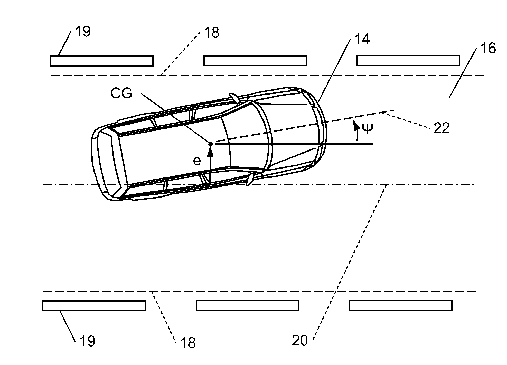
[0044]Referring now to the figures of the drawings in detail and first, particularly, to FIG. 1 thereof, there is shown a diagram of a planar single-track model for illustrating the coordinates, velocities and angles that are used when describing vehicle dynamics. The single-track vehicle model shown in FIG. 1 groups the left front tire and the right front tire of the vehicle into a front tire 10. The left rear tire and the right rear tire of the vehicle are grouped into a rear tire 12. Fyr and Fyf are lateral tire forces, i.e. the resultant forces on the front tire 10 and the rear tire 12. The wheel slip angle of the rear tire 12 is denoted by αrear. The wheel slip angle of the front tire 10 is denoted by αfront. The wheel slip angle α is the angle between the orientation of the tire and the velocity vector of the tire. The distance between the center of gravity CG of the vehicle and the front axle of the vehicle is indicated by a distance a. The distance between the center of grav...


PUM


Abstract

A method for controlling vehicle dynamics includes acquiring steering torque data indicative of forces acting on at least one tire of a vehicle and acquiring image data by capturing images of an area outside the vehicle. The friction coefficient between a tire of the vehicle and a road surface is determined as a function of vehicle data including at least the steering torque data. The lateral velocity of the vehicle is determined as a function of vehicle data including the steering torque data and / or the image data. A vehicle dynamics control is performed as a function of the lateral velocity and the friction coefficient.

Description

FIELD OF THE INVENTION[0001]The invention relates to a method for controlling vehicle dynamics, wherein vehicle data are ascertained and a vehicle dynamics control is performed based on the vehicle data.BACKGROUND OF THE INVENTION[0002]Vehicle dynamics control systems are generally developed for the purpose of improving safety and driving comfort. These systems are for example designed to detect and prevent skids, to prevent an unintended lane departure of the vehicle or to prevent an excessive roll motion of the vehicle.[0003]Control of a vehicle in emergency situations requires knowledge of a number of variables that define the vehicle state. One of the variables defining the vehicle state is the current friction coefficient between the tires of the vehicle and the road surface. Another variable defining the vehicle state is the current motion of the vehicle. If current values for the friction coefficient between the vehicle tires and the road surface and current values for the mo...

Claims


Application Information

Patent Timeline
Patent Type & Authority Applications(United States)
IPC IPC(8): B62D6/00
CPCB60T8/17557B60T2201/08B60T2201/083B60T2201/087B60T2210/12B60T2260/04B60T2260/06B62D6/003B62D6/006B62D15/025
Inventor SWITKES, JOSHUASTOSCHEK, ARNE
Owner VOLKSWAGEN GROUP OF AMERICA
Why Eureka
Try Eureka