Method And System For Energy Efficient Communication Among One Or More Interfaces In A Communication Path

a communication path and communication method technology, applied in the field of network communication, can solve problems such as significant increases in power consumption

Active Publication Date: 2010-05-06
AVAGO TECH INT SALES PTE LTD
View PDF38 Cites 52 Cited by
  • Summary
  • Abstract
  • Description
  • Claims
  • Application Information

AI Technical Summary

Benefits of technology

[0023]FIG. 7 is a flow chart illustrating exemplary steps for implementing an energy efficient network contr...

Problems solved by technology

Conventionally, however, increased data rates ofte...

Method used


Image

  • Method And System For Energy Efficient Communication Among One Or More Interfaces In A Communication Path
  • Method And System For Energy Efficient Communication Among One Or More Interfaces In A Communication Path
  • Method And System For Energy Efficient Communication Among One Or More Interfaces In A Communication Path

Examples


Embodiment Construction

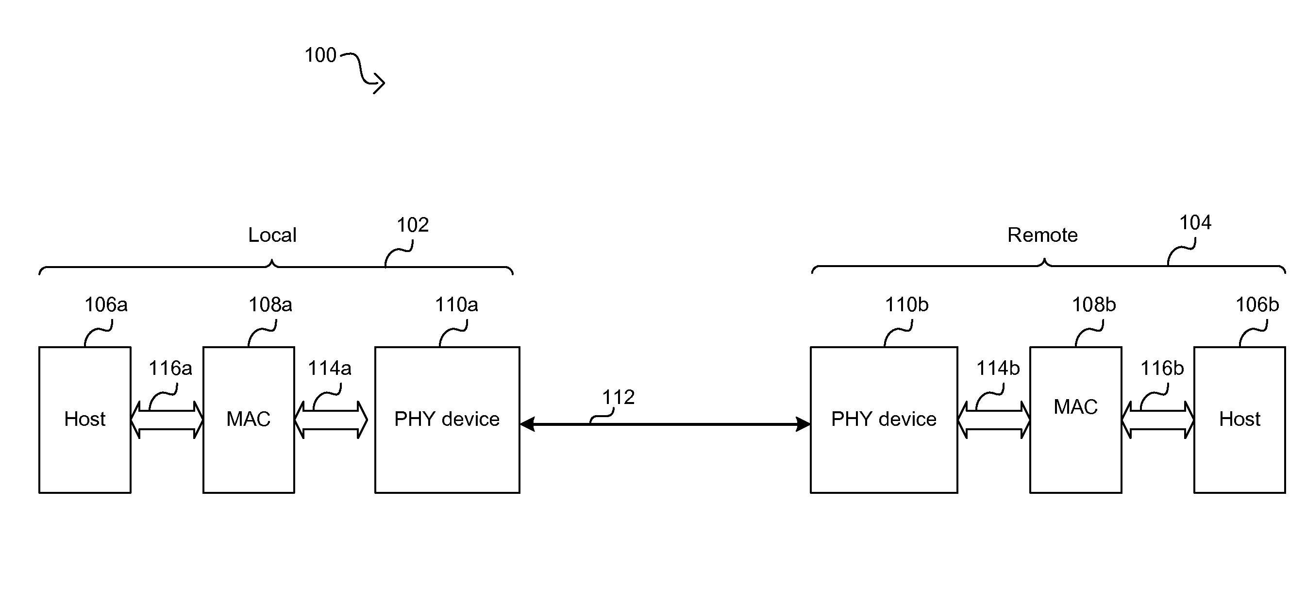
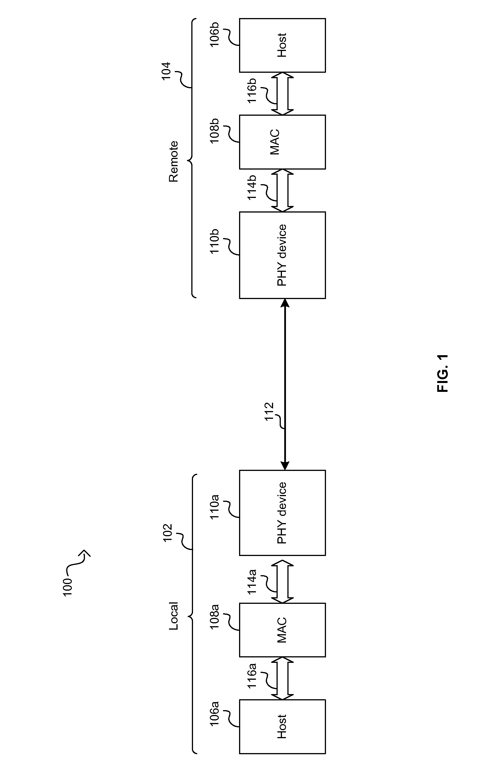
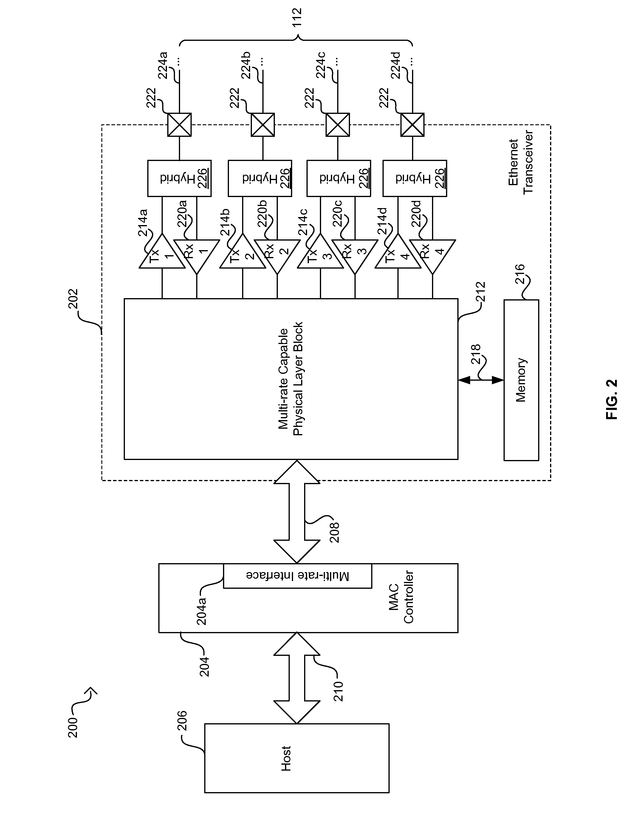
[0024]Certain embodiments of the invention can be found in a method and system for energy efficient communication among one or more interfaces in a communication path. In this regard, one or more of a plurality of network devices may be communicatively coupled via one or more serial and / or parallel interfaces. One or more circuits within the network devices may be operable to determine a power level mode of operation for the one or more interfaces and / or devices according to an energy efficient network communication control policy. The one or more circuits may configure the interfaces for the determined power level mode. In this regard, configuration in various interfaces may occur at one time instant or configuration may be cascaded sequentially through a plurality of interfaces. The plurality of network devices may comprise a physical layer device (PHY), a media access controller (MAC) and / or one or more higher OSI layer devices. The one or more of the interfaces may comprise a XG...


PUM


Abstract

Network devices coupled via serial and/or parallel interfaces may determine a power level mode of operation according to an energy efficient network communication control policy and may configure one or more of the interfaces for the lower power mode. The network devices may comprise a PHY, a MAC and/or higher layer devices. The interfaces may comprise a XGMII extender, a XAUI and/or a XFI device. The interfaces may comprise a backplane PHY, for example, a 10 GBASE-KR, a 10 GBASE-KX4 and/or a 1 GBASE-KX PHY which may perform FEC. The interfaces may comprise direct attach copper such as SFP+ and/or InfiniBand and/or 10 GBASE-CX4 PHYs. The interfaces may comprise a pluggable transceiver module. Energy efficient network control data may be communicated to and/or from the network devices which may enter and/or exit a lower power mode of operation.

Description

CROSS-REFERENCE TO RELATED APPLICATIONS / INCORPORATION BY REFERENCE[0001]This application makes reference to, claims priority to, and claims the benefit of U.S. Provisional Application Ser. No. 61 / 111,653, filed on Nov. 5, 2008.[0002]This application makes reference to:[0003]U.S. patent application Ser. No. 12 / 471,861 (Attorney Docket No. 20367US02) filed on May 26, 2009;[0004]U.S. patent application Ser. No. 12 / 470,785 (Attorney Docket No. 20368US02) filed on May 22, 2009;[0005]U.S. patent application Ser. No. 12 / 470,970 (Attorney Docket No. 20369US02) filed on May 22, 2009;[0006]U.S. patent application Ser. No. 12 / 474,557 (Attorney Docket No. 20370US02) filed on May 29, 2009;[0007]U.S. patent application Ser. No. 11 / 685,554 (Attorney Docket No. 18031US01) filed Mar. 13, 2007; and[0008]U.S. patent application Ser. No. 11 / 473,205 (Attorney Docket No. 17396US02) filed Jun. 22, 2006.[0009]Each of the above stated applications is hereby incorporated herein by reference in its entirety.F...

Claims


Application Information

Patent Timeline
IPC IPC(8): G06F1/00
CPCH04L12/12G06F1/3234Y02D30/32Y02D50/42Y02D30/30Y02D50/40Y02D30/00Y02D30/50
Inventor DIAB, WAEL WILLIAM
Owner AVAGO TECH INT SALES PTE LTD
Why Eureka
Try Eureka