Thermal management for fuel injectors

a fuel injector and thermal management technology, applied in the direction of efficient propulsion technologies, machines/engines, lighting and heating apparatus, etc., can solve the problems of stagnant fuel located within the main fuel circuit, fuel typically used in gas turbine engines is susceptible to breaking down into its constituent parts, and can be susceptible to coking. , to achieve the effect of reducing the flow of fuel

Active Publication Date: 2010-05-13
COLLINS ENGINE NOZZLES INC
View PDF12 Cites 20 Cited by
  • Summary
  • Abstract
  • Description
  • Claims
  • Application Information

AI Technical Summary

Benefits of technology

[0013]A method is provided for managing temperatures of fuel in a fuel injector for a gas turbine engine. The method includes cooling a fuel circuit of a first fuel injector by initiating or increasing fuel flow through the fuel circuit for combustion in a combustor of ...

Problems solved by technology

It is well known that fuels typically used in gas turbine engines are susceptible to breaking down into their constituent components when exposed to high temperatures.
For example, if wetted wall temperatures in fuel lines utilizing Jet A fuel are allowed to reach about 350° F., the fuel will begin to break down, which can lead to carbon formation within the fuel lines.
Since coking can build up and constrict and eventually block fuel passages, and since coke may flake off resulting in a large foreign object which can then clog or plug sensitive portions of the fuel injector, considerable efforts have been made to protect fuel circuits in fuel injectors and nozzles from high temperatures within gas turbine engines.
One difficulty associated with ...

Method used


Image

  • Thermal management for fuel injectors
  • Thermal management for fuel injectors
  • Thermal management for fuel injectors

Examples


Embodiment Construction

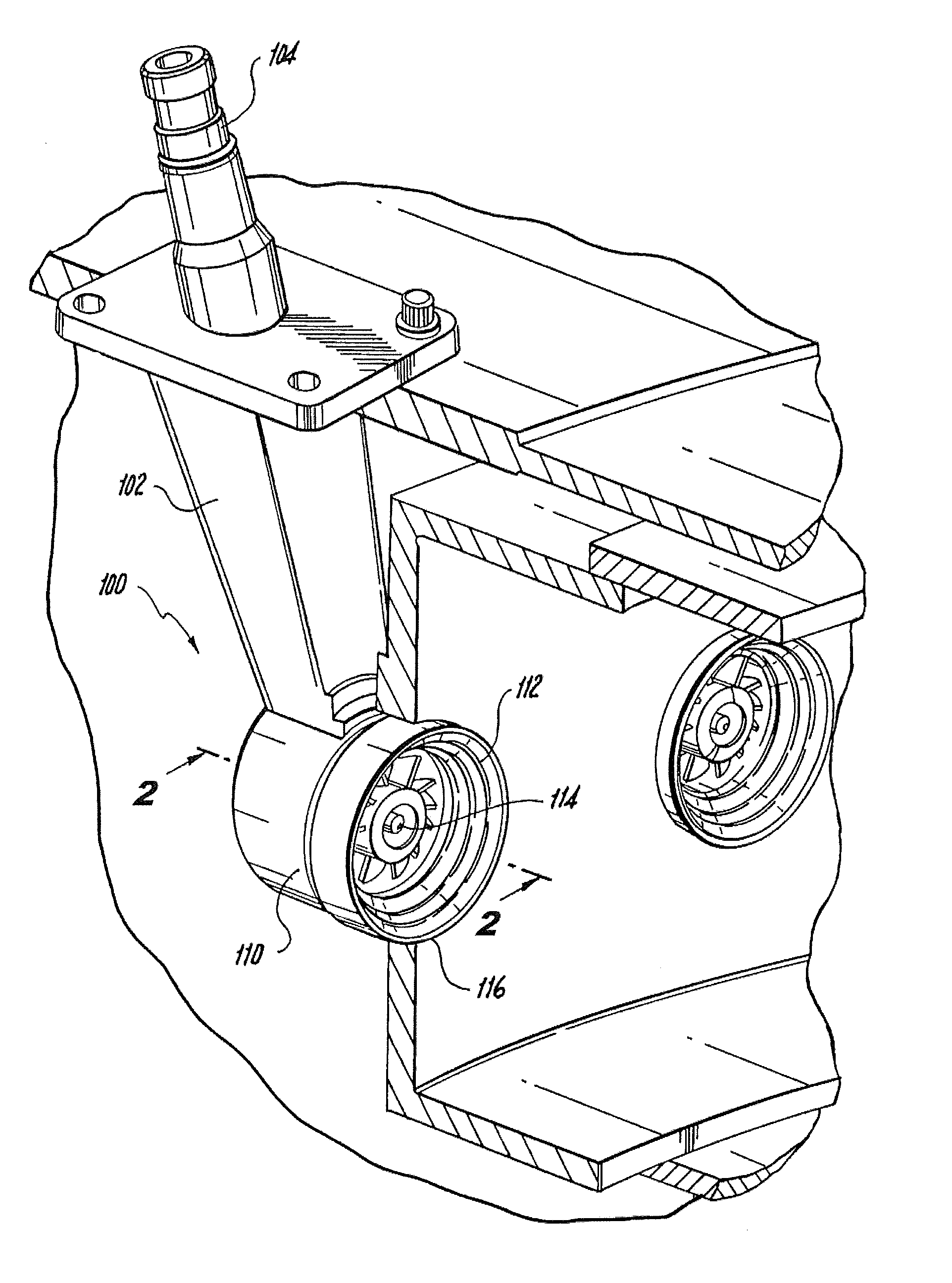
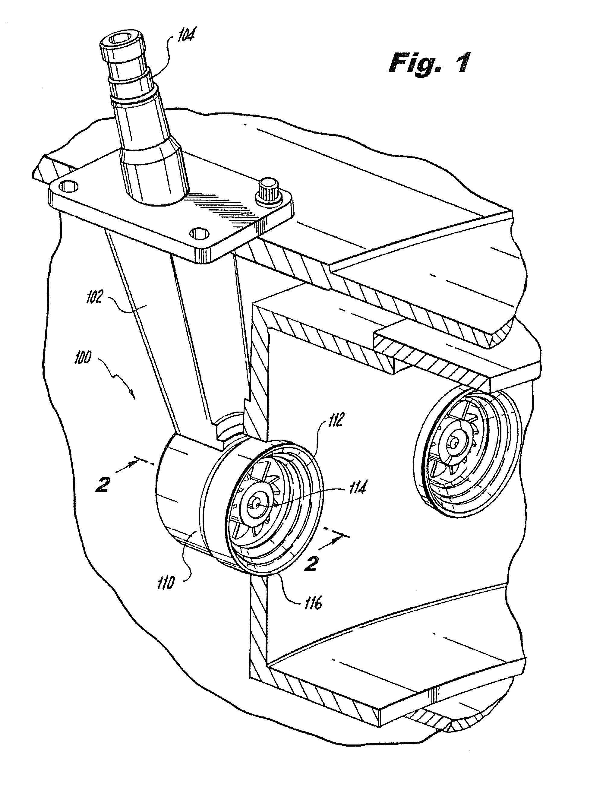
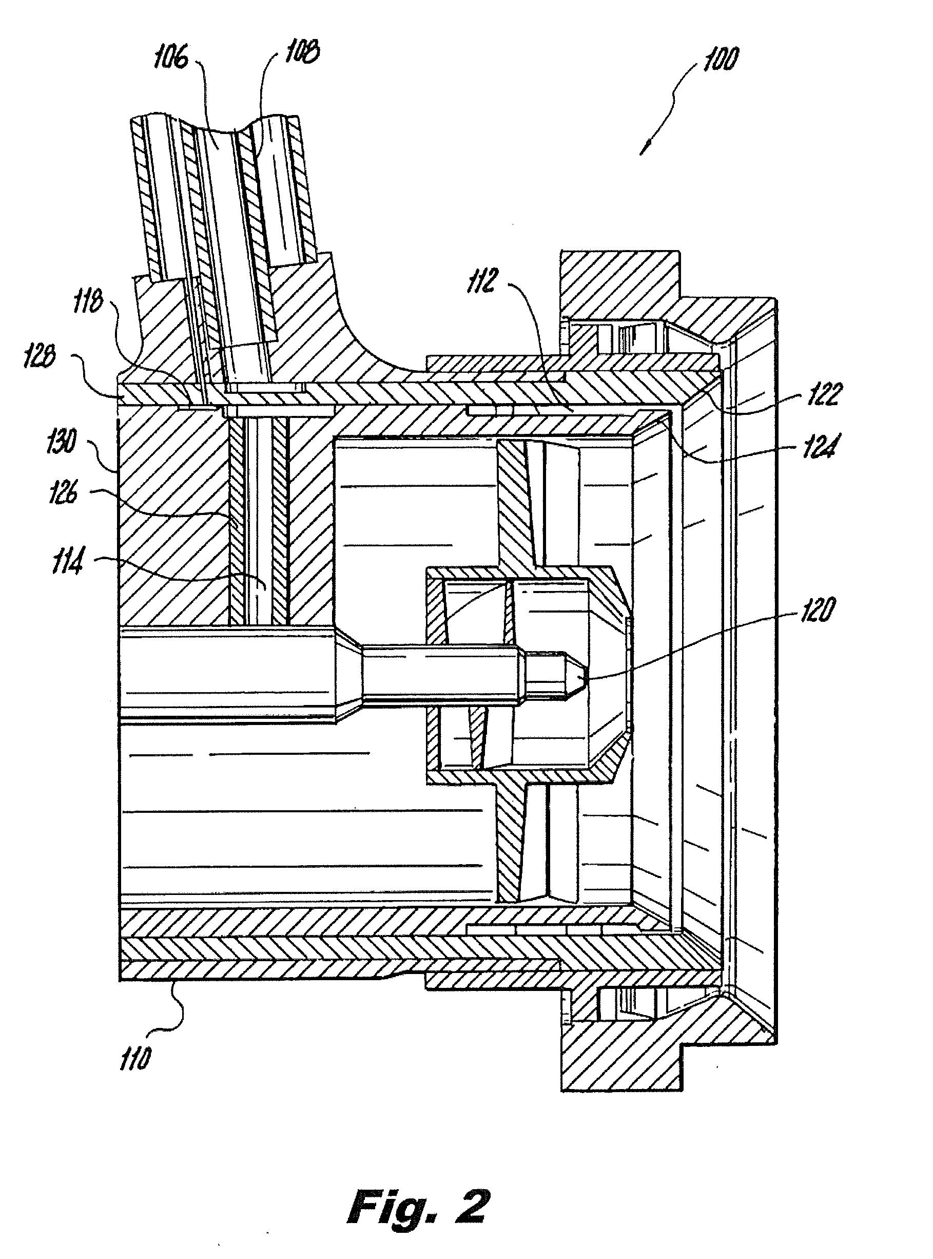
[0033]Reference will now be made to the drawings wherein like reference numerals identify similar structural features or aspects of the subject invention. In accordance with the invention, a fuel injector for a gas turbine engine is provided, including a feed arm having a fuel inlet fitting for delivering fuel to at least one fuel conduit extending through the feed arm. A nozzle body depends from the feed arm and has at least one fuel circuit extending therethrough. The fuel circuit is configured and adapted to receive fuel from the feed arm and to issue fuel from an exit orifice of the nozzle body. Sensing means are provided adjacent to the at least one fuel circuit. The sensing means are configured and adapted to provide temperature feedback in order to control fuel flow in the at least one fuel circuit to maintain fuel temperature within a predetermined range.

[0034]For purpose of explanation and illustration, and not limitation, a partial view of an exemplary embodiment of an inj...


PUM


Abstract

Methods of managing fuel temperatures in fuel injectors for gas turbine engines include cooling fuel circuits by initiating fuel flow therethrough using opened, closed, and semi-open control techniques. A fuel injector for a gas turbine engine includes a feed arm having a fuel inlet fitting for delivering fuel to at least one fuel conduit extending through the feed arm. A nozzle body depends from the feed arm and has at least one fuel circuit extending therethrough. The fuel circuit is configured and adapted to receive fuel from the feed arm and to issue fuel from an exit orifice of the nozzle body. Sensing means are provided adjacent to the at least one fuel circuit. The sensing means are configured and adapted to provide temperature feedback in order to control fuel flow in the at least one fuel circuit to maintain fuel temperature within a predetermined range.

Description

BACKGROUND OF THE INVENTION[0001]1. Field of the Invention[0002]The present invention relates to injectors and nozzles for high temperature applications, and more particularly, to fuel injectors and nozzles for gas turbine engines.[0003]2. Description of Related Art[0004]A variety of devices and methods are known in the art for injecting fuel into gas turbine engines. Of such devices, many are directed to injecting fuel into combustors of gas turbine engines under high temperature conditions while reducing or preventing carbon formation or coking within fuel passages.[0005]It is well known that fuels typically used in gas turbine engines are susceptible to breaking down into their constituent components when exposed to high temperatures. For example, if wetted wall temperatures in fuel lines utilizing Jet A fuel are allowed to reach about 350° F., the fuel will begin to break down, which can lead to carbon formation within the fuel lines. This phenomenon is known as coking. Since co...

Claims


Application Information

Patent Timeline
IPC IPC(8): F02C1/00
CPCF02C7/228F02C9/34F23D2206/10Y02T50/675F23R3/283F02C7/12F23D2900/11101Y02T50/60F23R3/343
Inventor GOEKE, JERRY L.THOMSON, NEAL A.WILLIAMS, BRANDON P.
Owner COLLINS ENGINE NOZZLES INC
Why Eureka
Try Eureka