Axial Heat Exchanger for Regulating the Temperature and Air Comfort in an Indoor Space

a heat exchanger and indoor space technology, applied in the direction of lighting and heating apparatus, tubular elements, stationary conduit assemblies, etc., can solve the problems of particularly unsuitable heat exchangers for regulating temperature, and achieve the effect of increasing the heat exchanging surface and the amount of dead spa

Inactive Publication Date: 2010-05-13
REHACT AB
View PDF10 Cites 12 Cited by
  • Summary
  • Abstract
  • Description
  • Claims
  • Application Information

AI Technical Summary

Benefits of technology

[0013]The heat exchanger disclosed below provides for an increased heat exchanging surface. The sheet members or fins that are connected to the inner channels are shaped to exploit the available space in a better way and fit better into a tubular outer channel. Due to the shape and positioning of the fins the amount of dead space—in particularly near the wall of the tubular outer channel—is reduced. The proposed fin structure can easily be applied to existing heat exchangers.

Problems solved by technology

US2006231242 disclosed an axial heat exchanger that is suitable for exchanging heat between a slowly flowing gas medium and a flow of a fluid or liquid medium having a low temperature difference, and they are particularly unsuitable as heat exchangers for regulating the temperature of air slowly flowing through the exchanger for the purpose of regulating the temperature and air comfort in a defined space, preferably in an in door space.

Method used


Image

  • Axial Heat Exchanger for Regulating the Temperature and Air Comfort in an Indoor Space
  • Axial Heat Exchanger for Regulating the Temperature and Air Comfort in an Indoor Space
  • Axial Heat Exchanger for Regulating the Temperature and Air Comfort in an Indoor Space

Examples


second embodiment

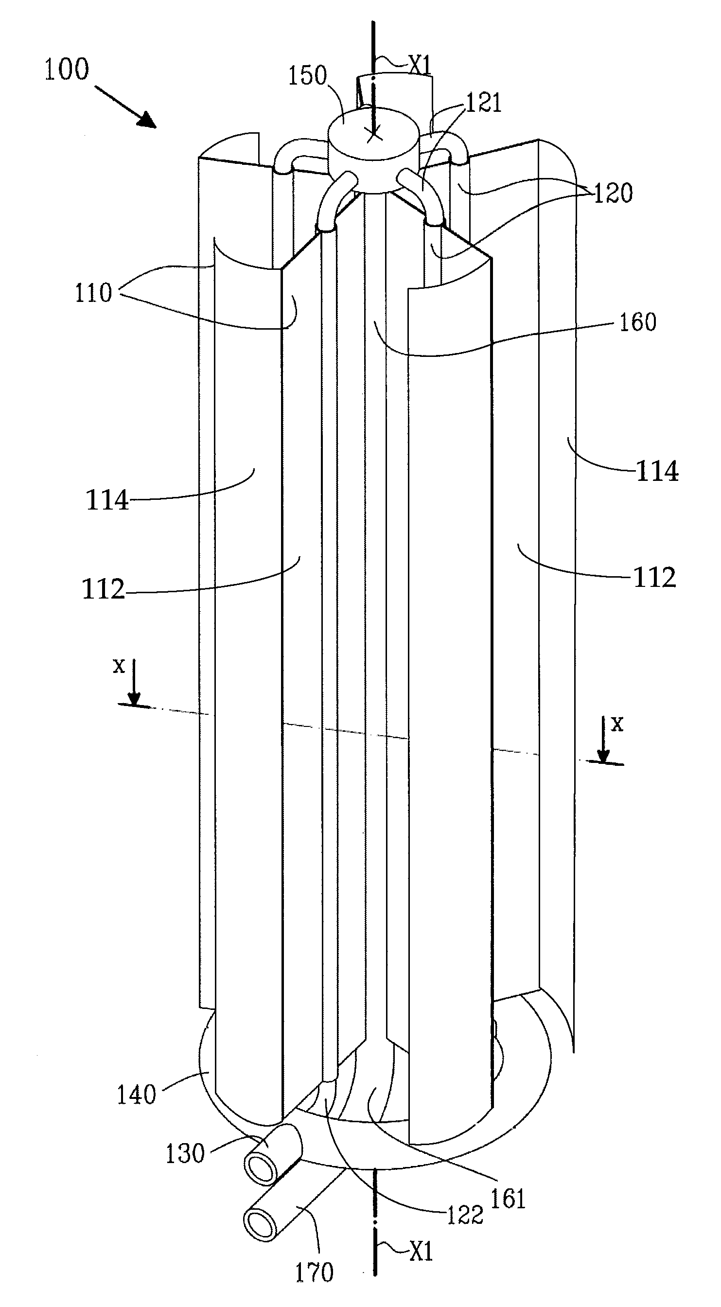
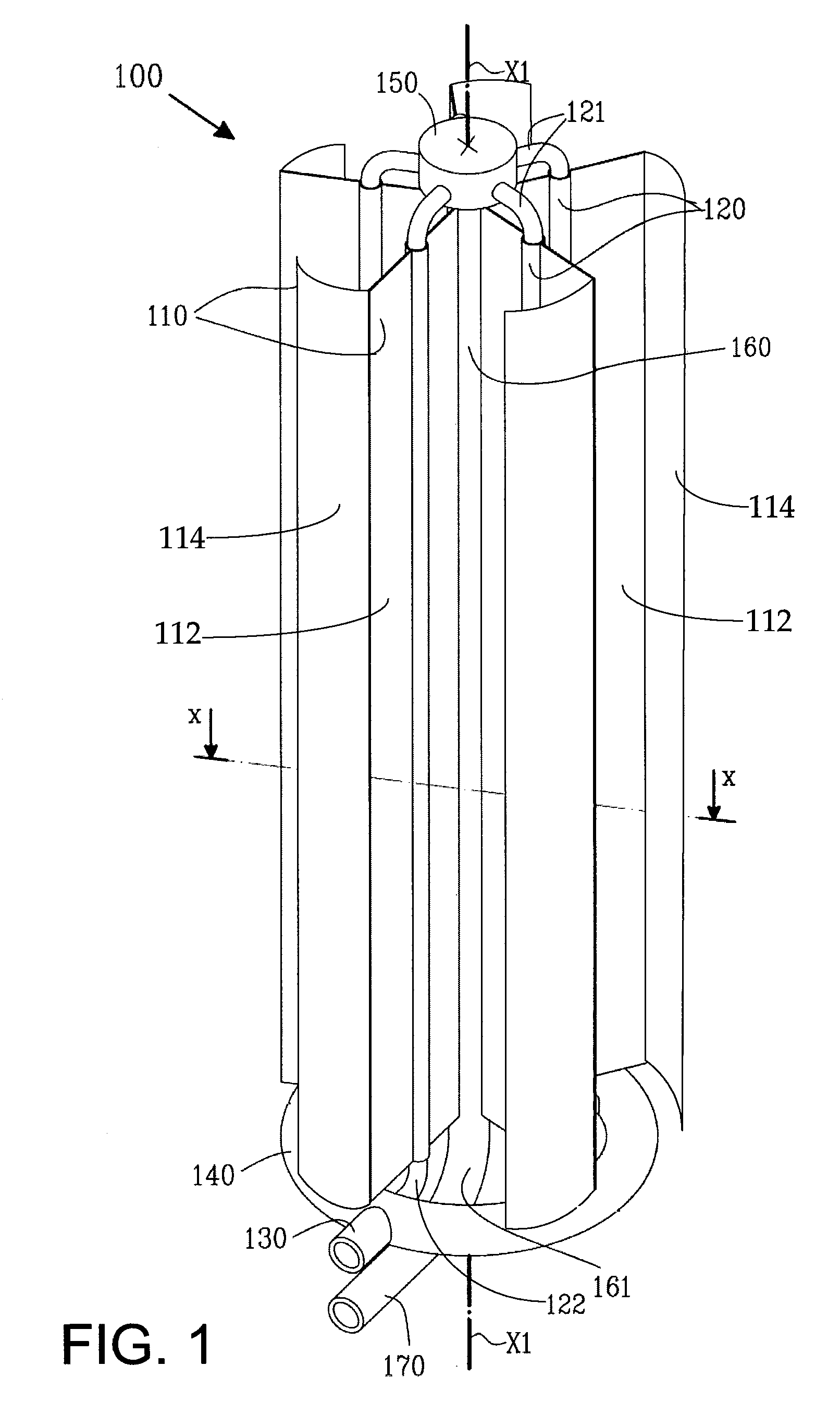
[0027]The sheets or fins 100 have first component 112 and a second component 114. The first component 112 of the sheets or fins 110 in FIGS. 1 and 2 extends in a radial direction, in addition to extending in an axial direction as previously explained. The radial direction extends substantially outwards from the centre or centre axis of the heat exchanging structure 100 towards the outer channel structure 200. This extends ends at a distance from the outer channel wall. The second component 114 of the sheets or fins 110 extends along the wall of the outer channel 200, i.e. substantially tangentially from the end of the first component 112 near the outer channel structure. The second component is in the shown embodiment curved, with a curvature identical or similar to the curvature of the outer channel. However, the second component could also be a not curved panel, as disclosed with the second embodiment below, or could be formed by two or more panels that are connected to one anothe...

third embodiment

[0040]FIG. 6 shows a schematic cross-section of another possible pattern for arranging the fins or sheets within an outer channel of an axial heat exchanger according to an embodiment of the present invention. This third embodiment has no central inner channel 60.

[0041]FIG. 7 shows a schematic cross-section of an axial heat exchanger according to fourth that is essentially the same as the previously discussed axial heat exchanger A1 shown in FIGS. 1-2. However, the outer channel 200 of the heat exchanger A1 with a circular cross section has been replaced in FIG. 6d by an outer channel structure 600 with a hexagonal cross section. The shape of the second components of the sheets 110 has been adapted correspondingly.

[0042]FIG. 8 shows the same axial heat exchanger as the one shown in FIG. 7, with the exception that the axial heat exchanger in FIG. 8 has four fins 110 instead of six fins 110 as in the heat exchanger shown in FIG. 7. It is especially advantageous to provide the rectangu...

first embodiment

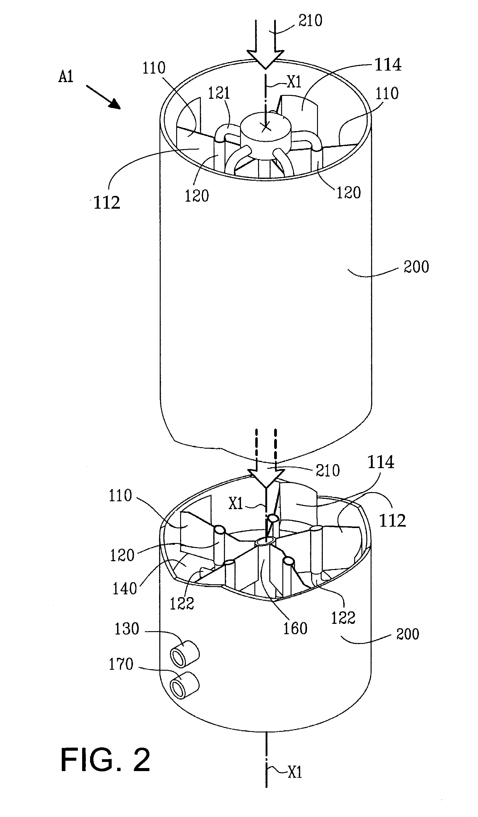
[0047]FIG. 4 shows a plurality of axial heat exchangers A1 according to the invention as discussed above in connection with FIGS. 1-2. The heat exchangers A1 have been arranged in parallel to enable a substantially simultaneous flow of a first medium (preferably air) through each the heat exchanger A1 along the medium channel or channels 210 as discussed above in connection with FIG. 2. The heat exchangers A1 must not be arranged side by side along a straight line as in FIG. 5b. On the contrary, the heat exchangers A1 may be arranged side by side in a circle or in a semi-circle, or in a square or according to some other polygonal pattern.

[0048]Each parallel heat exchanger A1 in FIG. 5b have been coupled to a supply channel arrangement extending along the parallel heat exchangers A1 for providing each exchanger with a second medium (preferably water). Accordingly, the lower distribution manifold 130 of each heat exchanger A1 has been coupled to a first supply channel 710, whereas the...


PUM


Abstract

The present invention offers an axial heat exchanger for exchanging heat between a gas medium and a fluid or liquid medium. The axial heat exchanger comprises a longitudinal and substantially axially extended outer channel that is adapted to enclose a flow of a first gas medium. The heat exchanger also comprises a plurality of substantially parallel inner channels that are adapted to enclose a flow of a second liquid medium. The inner channels are arranged inside the outer channel so as to extend substantially axially along the inside of said outer channel for enabling a transfer of heat between said first gas medium and said second liquid medium. At least one of the inner channels is joined with at least one elongated sheet. The sheet is arranged to extend substantially axially along the inner channel so as to substantially coincide with the direction of flow of the first gas medium through the outer channel. The sheet has a first component directed from the centre of the outer channel to the wall of the outer channel and a second component extending from the end of the first component along the wall of the outer channel.

Description

FIELD OF THE INVENTIONS[0001]The present invention relates to an axial heat exchanger for exchanging heat between two mediums, preferably a gas medium and a liquid medium and most preferably air and water. More particularly, the invention relates to a heat exchanger for regulating the air temperature and the air comfort in a defined space, preferably in an indoor space and more particularly to a heat exchanger that is suitable for exchanging heat between a slowly flowing gas medium and a flow of a fluid or liquid medium having a low temperature difference.BACKGROUND OF THE INVENTIONS[0002]1. Introduction[0003]Transfer of heat is a very common operation in connection with natural and human induced activities. Heat transfer mainly depends on three different mechanisms, namely conduction, convection and radiation.[0004]Heat transfer by conduction is essentially characterized by no observable motion of matter. In metallic solids there is motion of unbound electrons and in liquids there ...

Claims


Application Information

Patent Timeline
Patent Type & Authority Applications(United States)
IPC IPC(8): F28D15/00
CPCF28D1/0233F28D7/1669F28F1/14F28F1/22
Inventor HAWRANEK, JERZY
Owner REHACT AB
Why Eureka
Try Eureka