Electric drive

a technology of electric drive and drive shaft, applied in the direction of vehicle maintenance, vehicle cleaning, transportation and packaging, etc., can solve the problems of emitted interference radiation, and achieve the effect of improving the interference suppression

Inactive Publication Date: 2010-05-13
ROBERT BOSCH GMBH
View PDF8 Cites 9 Cited by
  • Summary
  • Abstract
  • Description
  • Claims
  • Application Information

AI Technical Summary

Benefits of technology

[0004]In contrast, the electric drive according to the invention has the advantage that the drive can be configured to be very compact overall since free space present in the preferably metal motor housing is used to partly accommodate the interference suppression apparatus. However, this particularly improves the interference suppression effect since the situation of feed lines from the motor space to the interference suppression means projecting into the shielded region of the gear mechanism housing and emitting interfering radiation there is avoided.

Problems solved by technology

In this case, feed lines to the interference suppression coils extend into the gear mechanism housing and there can emit interfering radiation which they receive in the production region of the interference, in particular through the commutator.

Method used


Image

  • Electric drive
  • Electric drive
  • Electric drive

Examples


Embodiment Construction

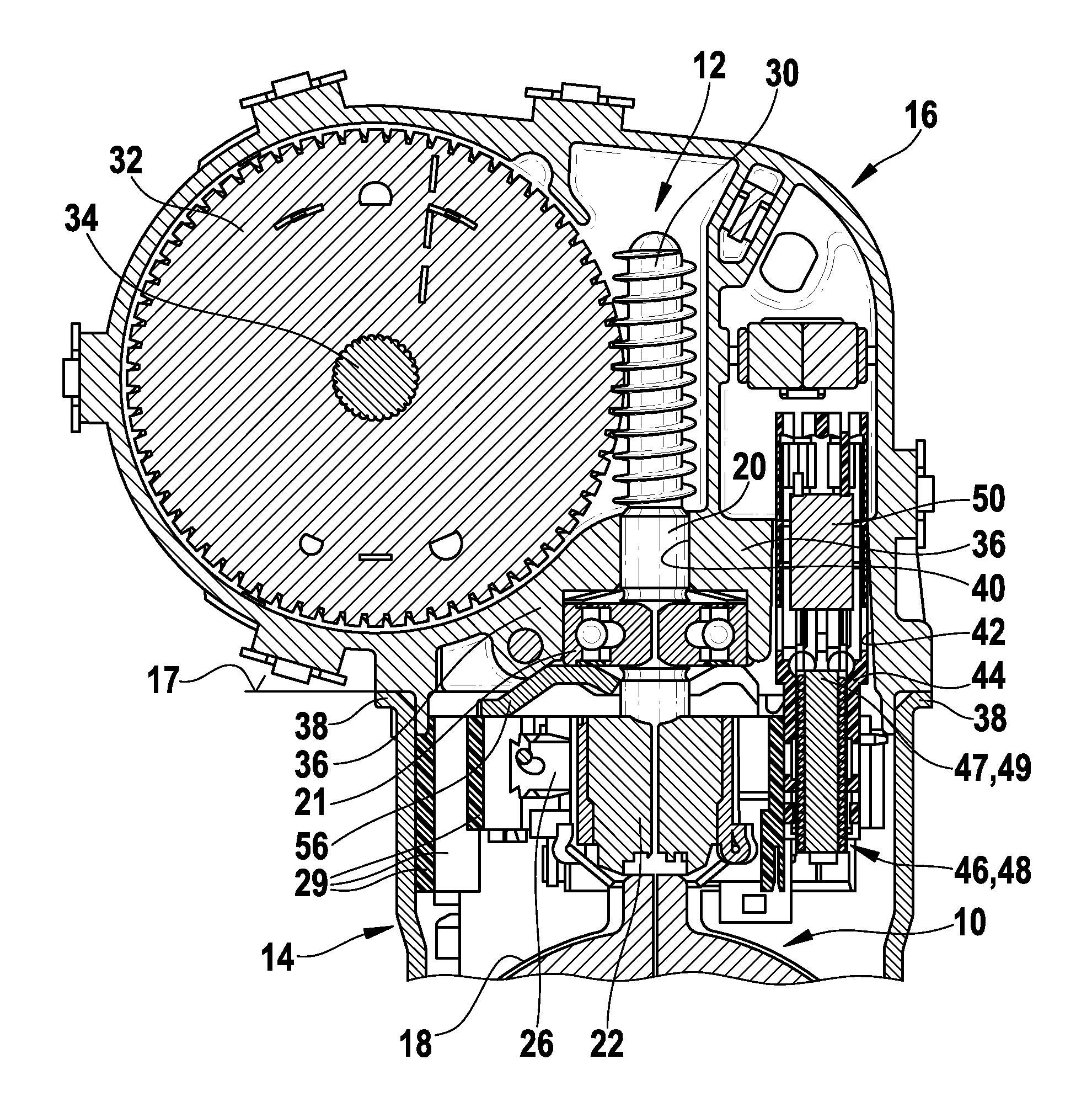
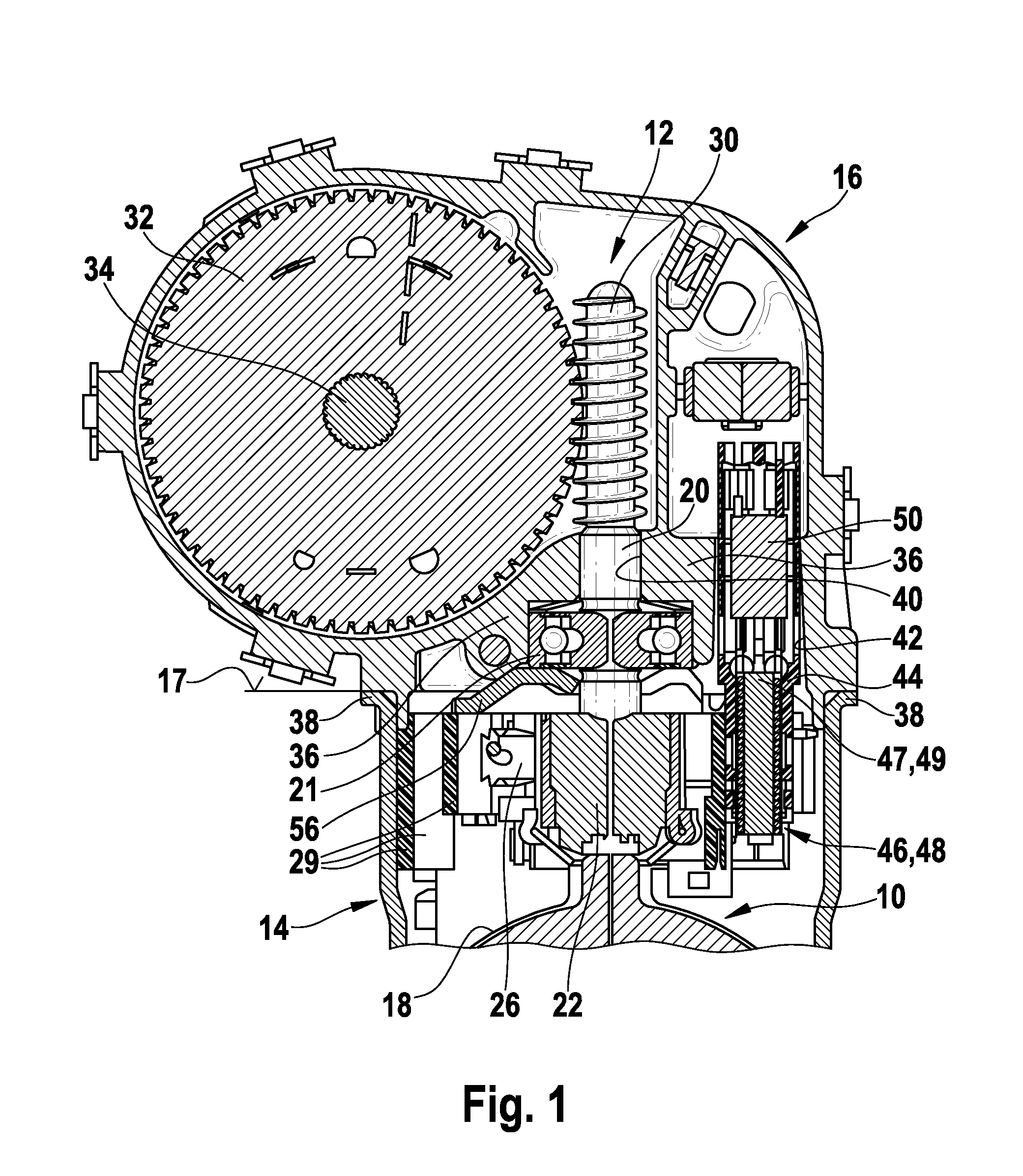
[0012]FIG. 1 illustrates an electric windshield wiper drive for a motor vehicle having an electric motor 10 and a gear mechanism 12 for reducing the motor rotation speed to a lower drive rotation speed. The motor 10 is arranged in a motor housing 14; the gear mechanism is arranged in a gear mechanism housing 16. FIG. 1 illustrates only the end of a winding 18 and a drive shaft 20 and a commutator 22 of the motor 10, the brushes 24, 26 and 28 (of which only brush 26 can be seen in FIG. 1) brushing on said commutator. The open end face 17 of the motor housing 14 defines the transition from the motor housing 14 to the gear mechanism housing 16.

[0013]The gear mechanism 12 essentially comprises a drive worm 30 which rotates with the drive shaft 20 of the motor 10 and meshes with a worm gear 32 which, for its part, is fixedly connected to an output drive shaft 34. The gear mechanism housing is closed off parallel to the sectional plane by a cover (not illustrated). A bearing plate 36 for ...


PUM


Abstract

The invention relates to an electric drive, particularly a windshield wiper drive for vehicles, comprising an electric motor (10) in a crucible-shaped, preferably metal, motor housing (14), a gearbox housing (16) that is attached to the motor housing (14), and an arrangement for the interference suppression of the motor (10). According to the invention, at least one choke coil (46, 48) for the interference suppression of the motor (10) is disposed in the transition region from the motor housing (14) to the gearbox housing (16), wherein in this transition region means (36, 56) are provided in order to shield the filtered coil end (47, 49) projecting into the gearbox housing (16) from the interfering radiation produced by the motor (10).

Description

BACKGROUND OF THE INVENTION[0001]The invention is based on an electric drive, in particular a windshield wiper drive for vehicles.[0002]DE 102 04 716 A1 already discloses an electric drive whose motor is arranged in a pot-like, metal housing which is combined with a gear mechanism housing. In this drive unit, an insulating base plate in the form of a mount for the motor brushes and further electrical components is situated in the transition region between the motor housing and the gear mechanism housing. Three choke coils for radio interference suppression of the motor are arranged on either side of the base plate, partly in the motor housing, partly in the gear mechanism housing without interference shielding.[0003]Furthermore, DE 39 30 144 C2 discloses integrally forming a flange-like, metal mount for a bearing of the motor shaft on the gear mechanism housing of a windshield wiper drive in the transition region to the motor housing. An apparatus for interference suppression of the...

Claims


Application Information

Patent Timeline
Patent Type & Authority Applications(United States)
IPC IPC(8): H02K11/02
CPCB60S1/166H02K11/026H02K7/1166B60S1/08H02K11/02H02K23/66
Inventor STUBNER, ARMINHEYDER, MARTINKOESTERS, MATTHIASMARTIN, NORBERT
Owner ROBERT BOSCH GMBH
Why Eureka
Try Eureka