Motor control apparatus

A technology for control devices and motors, applied in motor control, AC motor control, control systems, etc., can solve the problems of inability to shorten positioning adjustment time, fail to ensure stability, and consume time, and achieve shortened positioning adjustment time and interference suppression performance The effect of improving and shortening the positioning adjustment time

Active Publication Date: 2014-03-12
SANYO DENKI CO LTD
View PDF7 Cites 8 Cited by
  • Summary
  • Abstract
  • Description
  • Claims
  • Application Information

AI Technical Summary

Problems solved by technology

However, if the speed integral time constant is shortened, as described above, stability cannot be ensured due to the influence of resonance of the mechanical system
Moreover, in the structure of normal integral control, according to the delay of the speed relative to the speed command, the value in the speed integrator is accumulated, and it takes time until the value becomes 0 during positioning adjustment.
Therefore, there is a problem that the positioning adjustment time cannot be shortened.

Method used


Image

  • Motor control apparatus
  • Motor control apparatus
  • Motor control apparatus

Examples


Embodiment approach 1

[0035] [Configuration of the motor controller]

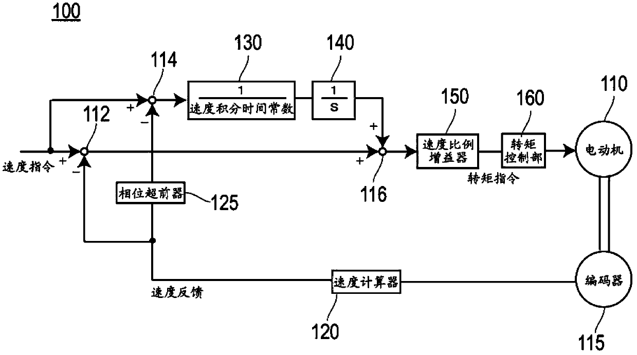
[0036] figure 1 It is a configuration diagram of the speed control system of the motor control device according to Embodiment 1. As shown in the figure, motor control device 100 according to Embodiment 1 includes phase advancer 125 , speed integral time constant adder 130 , integrator 140 , speed proportional gainer 150 , and torque control unit 160 .

[0037] The phase advancer 125 advances the phase of the speed feedback calculated by the speed calculator 120 by a set amount. For example, the phase of the speed feedback is advanced by a time equivalent to the hysteresis of the speed control system. The transfer function of the phase advancer 125 is preferably (1+ST2) / (1+ST1). However, the magnitude relationship between T1 and T2 in this case is T1

[0038] Also, the speed calculator 120 calculates a speed feedback based on the rotational position of the motor 110 detected by the encoder 115 .

[0039] The speed integr...

Embodiment approach 2

[0060] [Configuration of the motor controller]

[0061] Figure 5 It is a configuration diagram of a motor control device according to Embodiment 2. As shown in the figure, motor control device 200 according to Embodiment 2 includes position proportional gainer 220 , speed calculator 230 , speed control unit 240 , and torque control unit 250 .

[0062] The position proportional gainer 220 multiplies the position deviation obtained by subtracting the position feedback output from the encoder 215 from the position command at the accumulation point 212 by a proportional gain KP to output a speed command.

[0063] The speed calculator 230 is input with the position feedback output from the encoder 215, and calculates the speed feedback.

[0064] The speed control section 240 has the figure 1 The speed control system (phase advancer 125 , speed integral time constant adder 130 , integrator 140 , speed proportional gainer 150 ) of the motor control device 100 shown has the same c...

Embodiment approach 3

[0080] [Configuration of the motor controller]

[0081] Figure 8 It is a configuration diagram of a speed control system of a motor control device according to Embodiment 3. As shown in the figure, a motor control device 300 according to Embodiment 3 includes a phase advancer 325, a speed integral compensation low-pass filter 330, a speed integral time constant adder 340, an integrator 350, a speed proportional gainer 360, and a torque control Section 370.

[0082] The motor control device 300 according to Embodiment 3 differs from the motor control device 100 according to Embodiment 1 only in that it includes a speed integral compensation low-pass filter 330 , and the other configurations are the same. The speed control system of the motor control device 330 according to the third embodiment can also be applied to the speed control unit 240 of the motor control device 200 according to the second embodiment.

[0083] In addition, the respective functions of the phase advan...


PUM


Abstract

The invention provides a motor control apparatus capable of improving the performances of both interference suppression and positioning adjustment. A phase advancer (125) is configured to advance the phase of the speed feedback of a motor (110) in order to compensate the phase retardation of the speed feedback of the motor (110) within the high-frequency range. A time constant adapter (130) is configured to multiply the speed feedback difference between the advanced phase and speed commands sent by a computer by a time constant so as to suppress the interference effect. An integrator (140) is configured to integrate commands multiplied by the time constant adapter. A speed proportional gain (150) is configured to accumulate the commands, gain the accumulated commands by a speed ratio, and then output the torque command of the motor. The torque command is then input into a torque control part (160) so as to control the power supplied to the coil of the motor (110).

Description

technical field [0001] The present invention relates to a motor control device capable of improving both disturbance suppression performance and positioning adjustment performance. Background technique [0002] In general, machine tools use high-performance motor controls in order to be able to machine workpieces with high precision. The processing of workpieces always requires the improvement of processing quality and productivity, so the speed control system of the motor control device is also required to improve the control performance, especially the improvement of interference suppression performance and positioning adjustment performance. [0003] There is interference such as friction in the mechanical system. Interference prevents the motors that drive the machine tool from operating as instructed. For example, in the positioning control of a machine tool, the positioning adjustment time varies for each position under the influence of the friction of the mechanical...

Claims


Application Information

Patent Timeline
Patent Type & Authority Applications(China)
IPC IPC(8): H02P23/00H02P29/00
CPCH02P23/0004H02P23/14H02P2205/07
Inventor 井出勇治
Owner SANYO DENKI CO LTD
Why Eureka
Try Eureka