Magnetic sensor and sensitivity measuring method thereof

Active Publication Date: 2010-05-13
ASAHI KASEI ELECTRONICS CO LTD
View PDF4 Cites 55 Cited by
  • Summary
  • Abstract
  • Description
  • Claims
  • Application Information

AI Technical Summary

Problems solved by technology

The method, however, cannot correct sensitivity variations involved in the element sensitivity variations of the individual magnetic sensors or the misalignment of the magnetic substance.
This presents a problem of entailing test cost.
This construction, however, cannot generate any magnetic fields other than the vertical direct

Method used


Image

  • Magnetic sensor and sensitivity measuring method thereof
  • Magnetic sensor and sensitivity measuring method thereof
  • Magnetic sensor and sensitivity measuring method thereof

Examples


Embodiment Construction

[0063]The embodiment in accordance with the present invention will now be described with reference to the accompanying drawings.

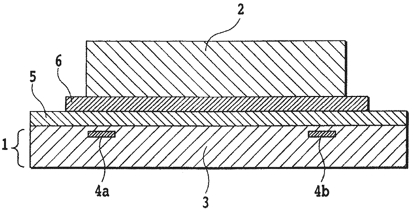
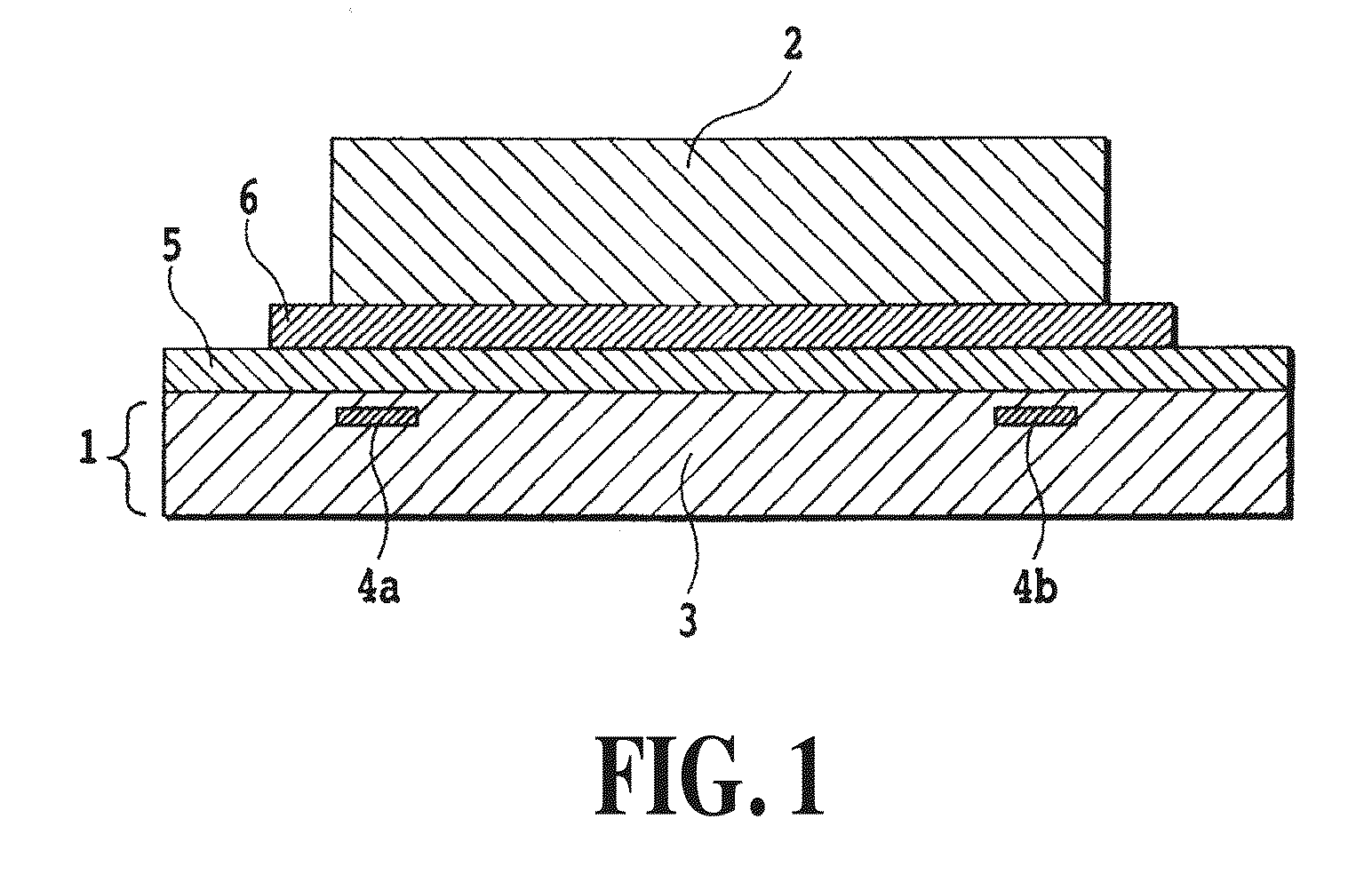
[0064]In the following embodiments, although magnetic sensitivity surfaces are described by way of example of Hall elements, the present invention is applicable not only to the Hall elements, but also to any magnetic sensitivity surfaces capable of detecting a magnetic field perpendicular to the magnetic substance (magnetoresistance element and the like).

[0065]FIG. 3 is a diagram showing magnetic flux distribution around Hall elements in a magnetic sensor in accordance with the present invention. In FIG. 3, a curved line represented by a solid line shows horizontal-to-vertical magnetic transformation characteristics by the magnetic convergence function of a magnetic substance. It has peak values at edges of the semiconductor substrate 13, and has gentle slopes toward the center. Incidentally, in FIG. 3, reference numerals 14a and 14b designate Hall elements...


PUM


Abstract

The present invention relates to a magnetic sensor with a sensitivity measuring function and a method thereof. Magnetic sensitivity surfaces detect flux density, and a switching unit extracts magnetic field intensity information of each axis, and inputs it to a sensitivity calculating unit. The sensitivity calculating unit calculates the sensitivity from the magnetic field intensity information about the individual axes from the magnetic sensitivity surfaces. The sensitivity calculating unit includes an axial component analyzing unit for analyzing the flux density from the magnetic sensitivity surfaces into magnetic components of the individual axes; a sensitivity decision unit for deciding the sensitivity by comparing the individual axial components of the magnetic field intensity from the axial component analyzing unit with a reference value; and a sensitivity correction unit for carrying out sensitivity correction in accordance with the sensitivity information from the sensitivity decision unit.

Description

TECHNICAL FIELD[0001]The present invention relates to a magnetic sensor with a sensitivity measuring function and a sensitivity measuring method thereof, and more particularly to a magnetic sensor and a sensitivity measuring method thereof for providing a sensitivity measuring function to a magnetic sensor having a semiconductor substrate on which a plurality of Hall elements are provided separately from each other and a magnetic substance mounted on the semiconductor substrate.BACKGROUND ART[0002]As a magnetic sensor, a device has conventionally been well known which has Hall elements provided on a semiconductor substrate and a magnetic substance (magnetic flux concentrator) that is mounted on the Hall elements and has a magnetic convergence function, and which causes magnetic convergence and detects the magnetic field intensity thereof with the Hall elements.[0003]FIG. 1 is a structural view for explaining this type of magnetic sensor. A semiconductor circuit 1 comprises a semicon...

Claims


Application Information

Patent Timeline
IPC IPC(8): G01N27/72G01R33/02G01R33/00
CPCG01R35/005G01R33/07G01R33/02G01R33/0206
Inventor YAMASHITA, MASAYAYAMAGATA, YO
Owner ASAHI KASEI ELECTRONICS CO LTD
Why Eureka
Try Eureka