
Self scheduling flow system with readout as infrastructure

a flow system and readout technology, applied in road vehicle traffic control, traffic signals, instruments, etc., can solve problems such as excessive traffic, danger, and crowding, and achieve the effect of increasing the mobility of traffi

Active Publication Date: 2010-05-13
FREE JAMES JACOB
View PDF10 Cites 20 Cited by
  • Summary
  • Abstract
  • Description
  • Claims
  • Application Information

AI Technical Summary

Benefits of technology

[0029]Multiple readouts that are emplaced among these void times and places (within X) could serve two main purposes. First, they may help to enhance resolution not only visual resolution which is important, but speed outputs per time resolution and arrival times within the Tng resolution. If there are multiple readout emplacements, a late or early few seconds within Tng hierarchy place could be “corrected” and the vehicle could more accurately get to it's intended spot in FLOW pattern as it passes through the green phase.
[0040]Another object is to provide for a way that traffic can get through a green part of the signal when that signal is first encountered as well as when that signal is in a series of signals that are far apart enough to be considered as first encountered.

Problems solved by technology

If there is a perceivable way to get into a green zone, the vehicles could easily exceed, and in some cases would have to exceed the speed limit to gain access to the green zone ahead, thereby creating a dangerous situation.
What is especially dangerous, is that traffic would build up and crowd in on the trailing part of a green zone where it had to exceed the speed limit in order to get there.
So not only would traffic bunch up at too large of an amount too rapidly, it would also do it at a speed greater than the speed limit.
An infrastructure difficulty with Villimon, Hawkes (U.S. Pat. No. 3,544,959 December 1970), Marton et al is the coordination of moving pattern of switching lights along with what may turn out as a large amount of power to run them.
Also, it would be very expensive to operate.
It does not work for traffic going in opposite directions on the same road; i.e. bi-directional.
Green Wave will also not be effective in essentially isolated signals or signals far enough apart that they could be treated as isolated.
Green wave attempts for opposite (perpendicular) directions that may involve block by block scenarios get more complex and may provide a diminishing return of mobility at higher complexity, less reliability, less dependability, and less safety; i.e. becoming more dangerous.
While Villemain, Hawkes, Marton, Raswant, et al all identify some kind of green zone, as well as “vacated area”, these inventions lack (along with a method of safely consolidating traffic) any kind of clear way instruct the traffic to go into the green zone.
There is no method or parameters that they provide, and any idea that they do have is detrimental to safety in a sense that they encourage speeding to catch up with a green zone.

Method used


Image

  • Self scheduling flow system with readout as infrastructure
  • Self scheduling flow system with readout as infrastructure
  • Self scheduling flow system with readout as infrastructure

Examples


Embodiment Construction

[0058]The following preferred embodiment is proposed for the purposes of disclosure and clarification. By no means and under no circumstances does it represent the only form the invention could take.

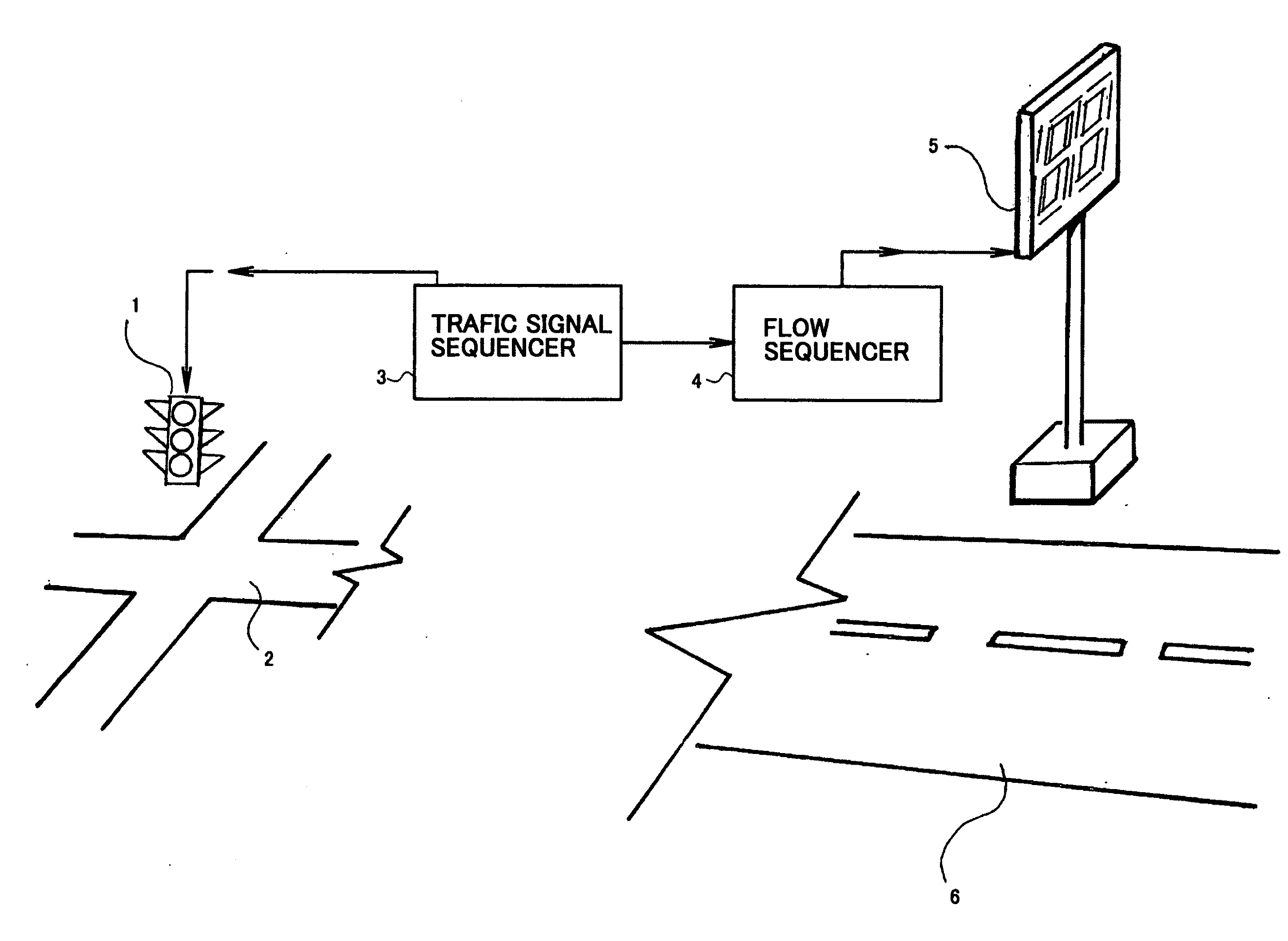
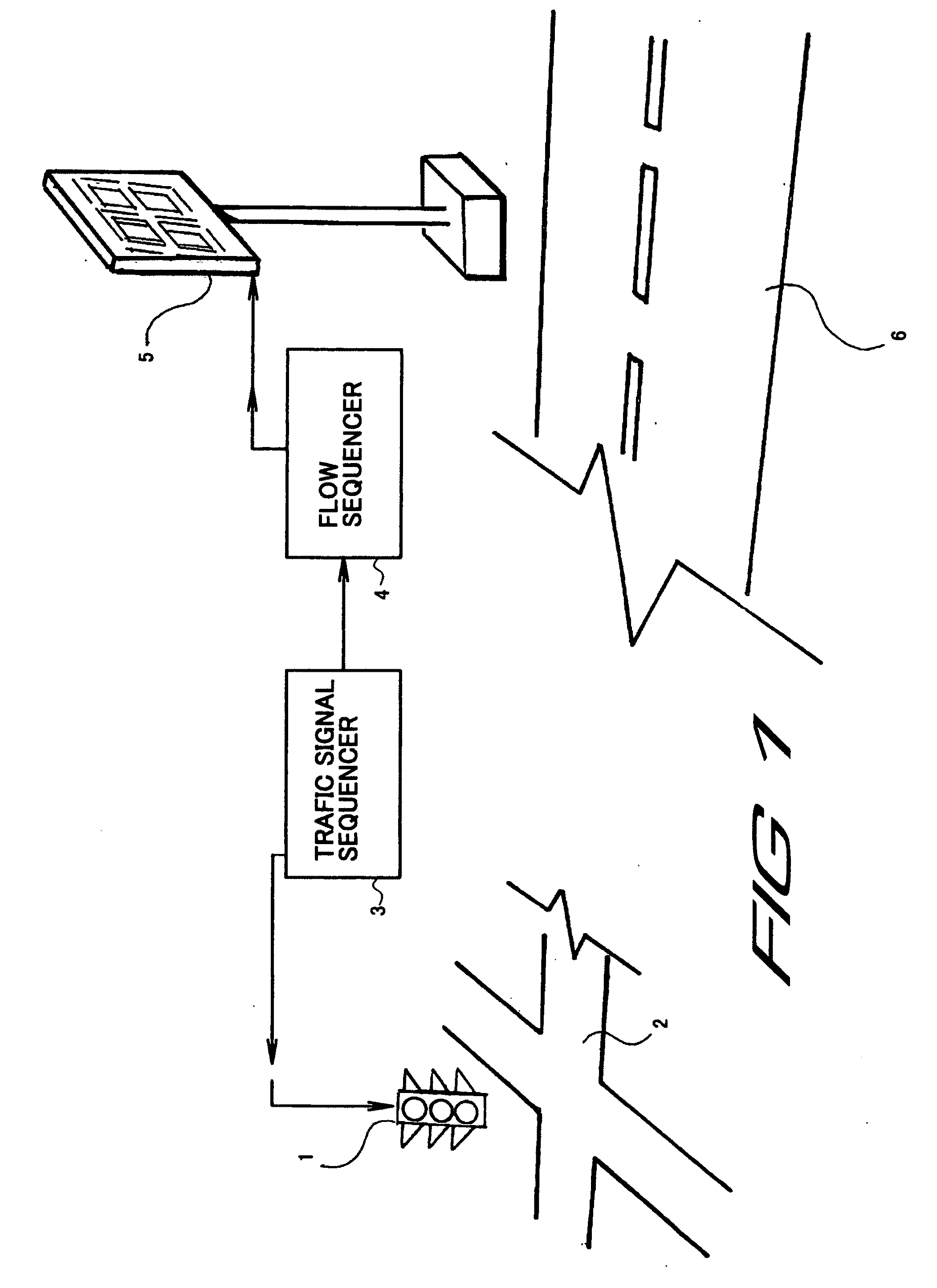
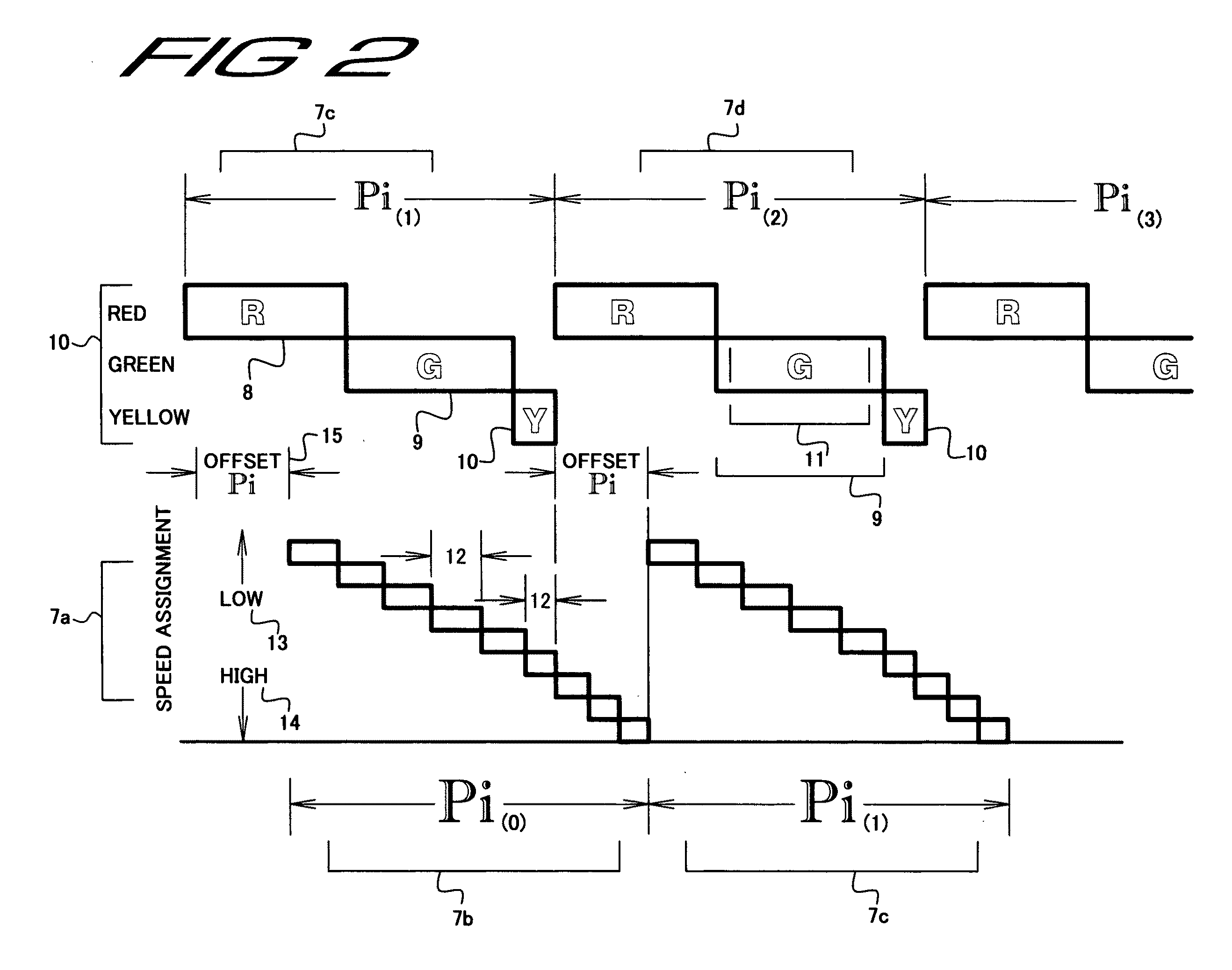
[0059]In FIG. [1] a traffic signal (1) controls intersection (2) being governed by traffic sequencer (3) which times itself with Fast Lane On Warning; FLOW sequencer (4) which sends sequences out to changing digits emplaced readout (5) a far distance away on roadway (6) while traffic “RGY” service cycle (7) has service cycle period Pi, that includes red cycle or phase (8), green cycle or phase (9) yellow cycle or phase (10), with a “net” green (11) being part of the green phase (9) in FIG. [2]. The same period Pi is the sum of the FLOW sequences coming out as speed assignments (12) including linear range. Low speed assignments (13) range to high speed assignments (14). After considering cycle start offset (15), speed assignments of Pi-0 (7b) will correspond to net green phase Pi-1 (7c), ...


PUM


Abstract

An invention regarding traffic flow management “Fast Lane On Warning” (FLOW) is disclosed whereby individual vehicles are informed and told what speed to go in order to pass through a traffic signal while the light is green. A FLOW (“fast lane on warning”) director sequencer works in conjunction with a traffic signal sequencer (commonly known in the art), both of which have the same service cycle period Pi. The (RGY) type phases and FLOW readout phases are set for each unique particular intersection. While the traffic sequencer controls repeating RGY cycles, the flow director sequencer instructs, generates, transmits repeating cycles of changeable readouts on one or more roadside unit (RSU) emplacements positioned up the road from the traffic signal for one or more lanes in one or more directions. These changing speed assignments or readouts, individually perceived by motorists, guide in motorists such that by the time they pass through the intersection, they will do so while the traffic signal is green, regardless of any random pattern of traffic individual motorists may have been in as they approached the emplacements.

Description

REFERENCES[0001]U.S. Pat. No. 3,302,168 January 1967 Gray 340 / 932[0002]U.S. Pat. No. 3,529,284 September 1970 Villemain 340 / 942[0003]U.S. Pat. No. 3,544,959 December 1970 Hawks 340 / 942[0004]U.S. Pat. No. 3,750,099 July 1973 Proctor 340 / 932[0005]U.S. Pat. No. 3,872,423 July 1975 Yeakley 340 / 932[0006]U.S. Pat. No. 5,278,554 Jan. 11, 1994 Marton 340 / 942[0007]U.S. Pat. No. 5,959,553 Sep. 28, 1999 Raswant, 340 / 907[0008]U.S. Pat. No. 5,821,878 Oct. 13, 1998 Raswant 340 / 907[0009]U.S. Pat. No. 5,330,278 Jul. 19, 1994 Raswant 404 / 1[0010]U.S. Pat. No. 6,424,271 Jul. 23, 2002 Raswant 340 / 907[0011]Free, James Paper Published at Intelligent Transportation Society of America Jun. 3, 2009FIELD[0012]This invention relates to increased mobility in traffic, systems that autonomously schedule and tell vehicles how fast to go to get through green phase, green waves for bi-directional traffic in perpendicular directions where groups take turns going through green phase.BACKGROUND[0013]Due to the increas...

Claims


Application Information

Patent Timeline
Patent Type & Authority Applications(United States)
IPC IPC(8): G08G1/096
CPCG08G1/07
Inventor FREE, JAMES J.
Owner FREE JAMES JACOB
Learn More