
Membrane deformable optical device having improved actuation

Active Publication Date: 2010-05-13
WEBSTER CAPITAL LLC
View PDF8 Cites 67 Cited by
  • Summary
  • Abstract
  • Description
  • Claims
  • Application Information

AI Technical Summary

Benefits of technology

[0017]It is a further object of the invention of the invention to increase the effectiveness of the actuating means to deform the membrane so as to obtain a greater deformation of the membrane than could be obtained in the prior art.
[0018]A further object of the invention is to reduce the electric power consumption of the optical device both during the actuation of the actuating means and when they are static and maintain the membrane in a deformed position.
[0036]In the case in which the optical device comprises a plurality of membranes, a single cover may protect the membranes.
[0041]To prevent the degradation of the optical performance of the optical device due to the effects of gravity, it is preferable for the second fluid to have a density as close as possible to that of the first fluid regardless of whether the operating mode is in transmission or in reflexion.

Problems solved by technology

The mechanical structures associated with the membranes are all highly complex, and are too expensive for an application in compact camera modules like those integrated in camera-telephones.
One major drawback is associated with the type of actuation, which is bulky and complex, in particular because of the container, and not highly effective.
Moreover, the seals to be obtained are not all located in the same plane, thus requiring delicate handling of films or plates, which considerably complicates the method employed and the tooling required.
These techniques are not compatible with conventional methods for manufacturing batches employed for the production of microelectromechanical systems MEMS or micro optoelectromechanical systems MOEMS.
Their cost consequently remains high and their size also.
Moreover, during the assembly, it is difficult to position the transparent elastic film at the peripheral elastic film and to position the ring perfectly during its transfer to the peripheral elastic film.
Another difficulty is the perfect positioning of the actuators with regard to the ring.
An imperfect positioning gives rise to optical aberrations, which degrade the quality of the image obtained.
If not, optical aberrations are produced and degrade the quality of the image obtained.
It is very difficult to achieve these results with the many seals required.
Furthermore, since several films are sealed together hermetically, like a patchwork, and to the container for encapsulating the liquid, the risk of leakage is not negligible.
Another drawback is associated with the electric power consumption of the actuating means on the one hand, when they actuate the membrane, but also when they maintain the membrane in a given position.

Method used


Image

  • Membrane deformable optical device having improved actuation
  • Membrane deformable optical device having improved actuation
  • Membrane deformable optical device having improved actuation

Examples


Embodiment Construction

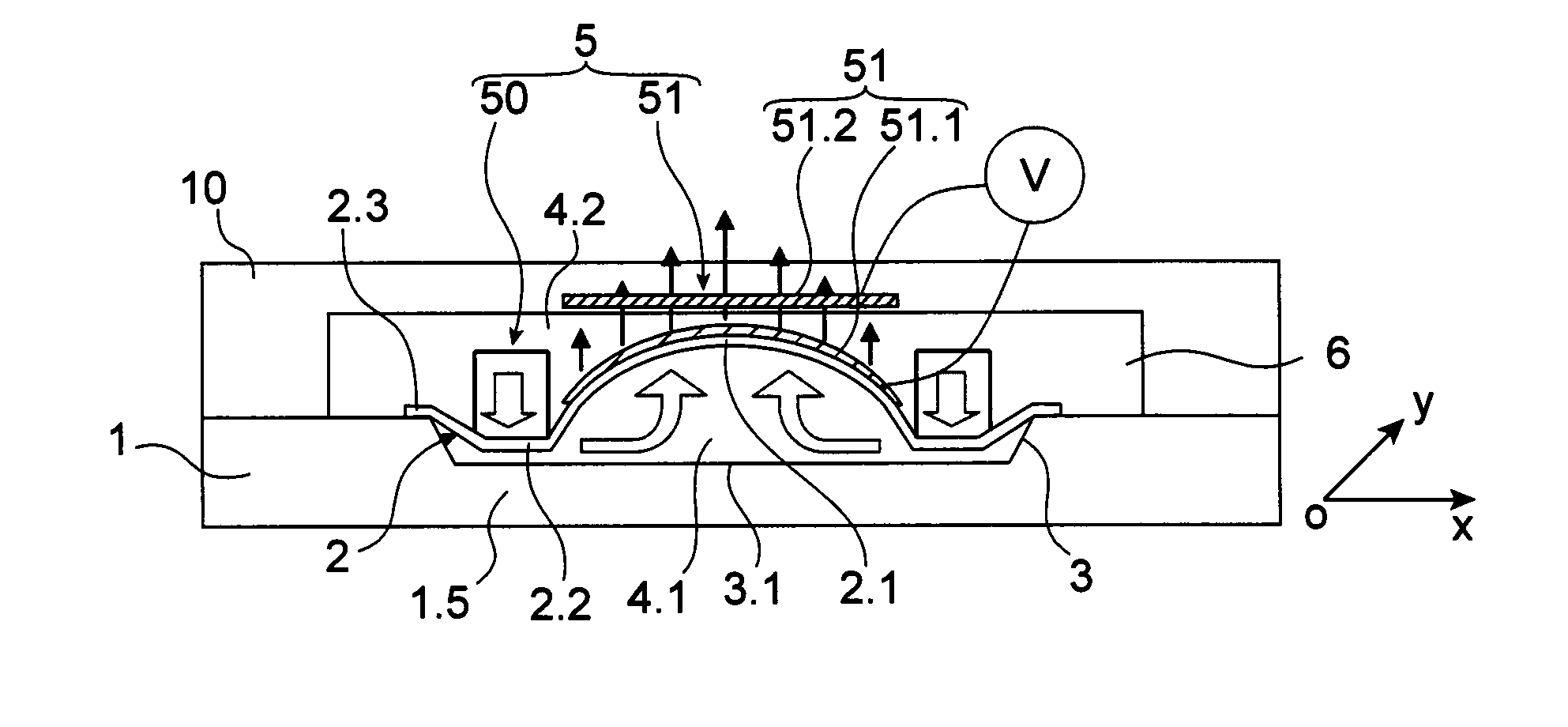
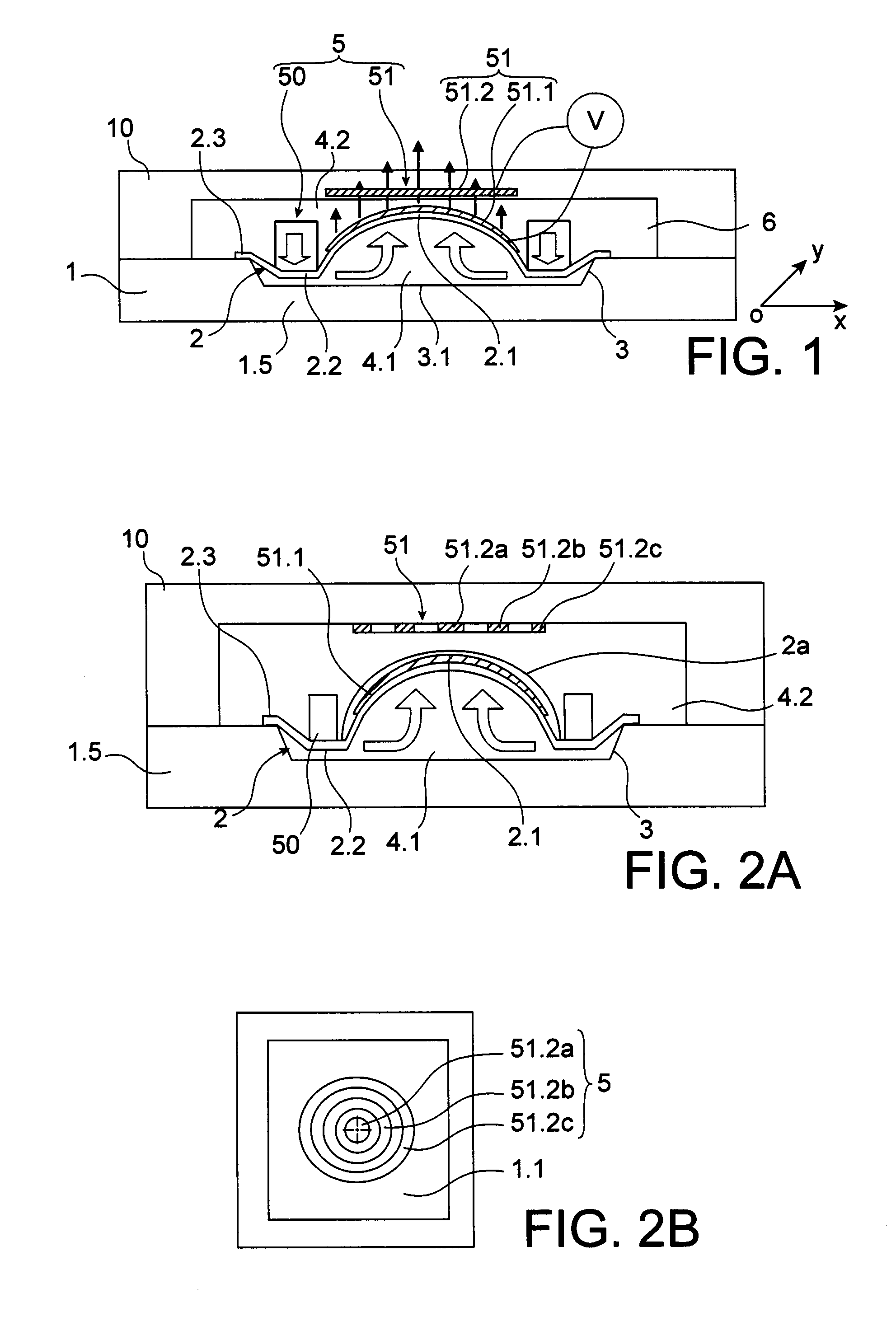
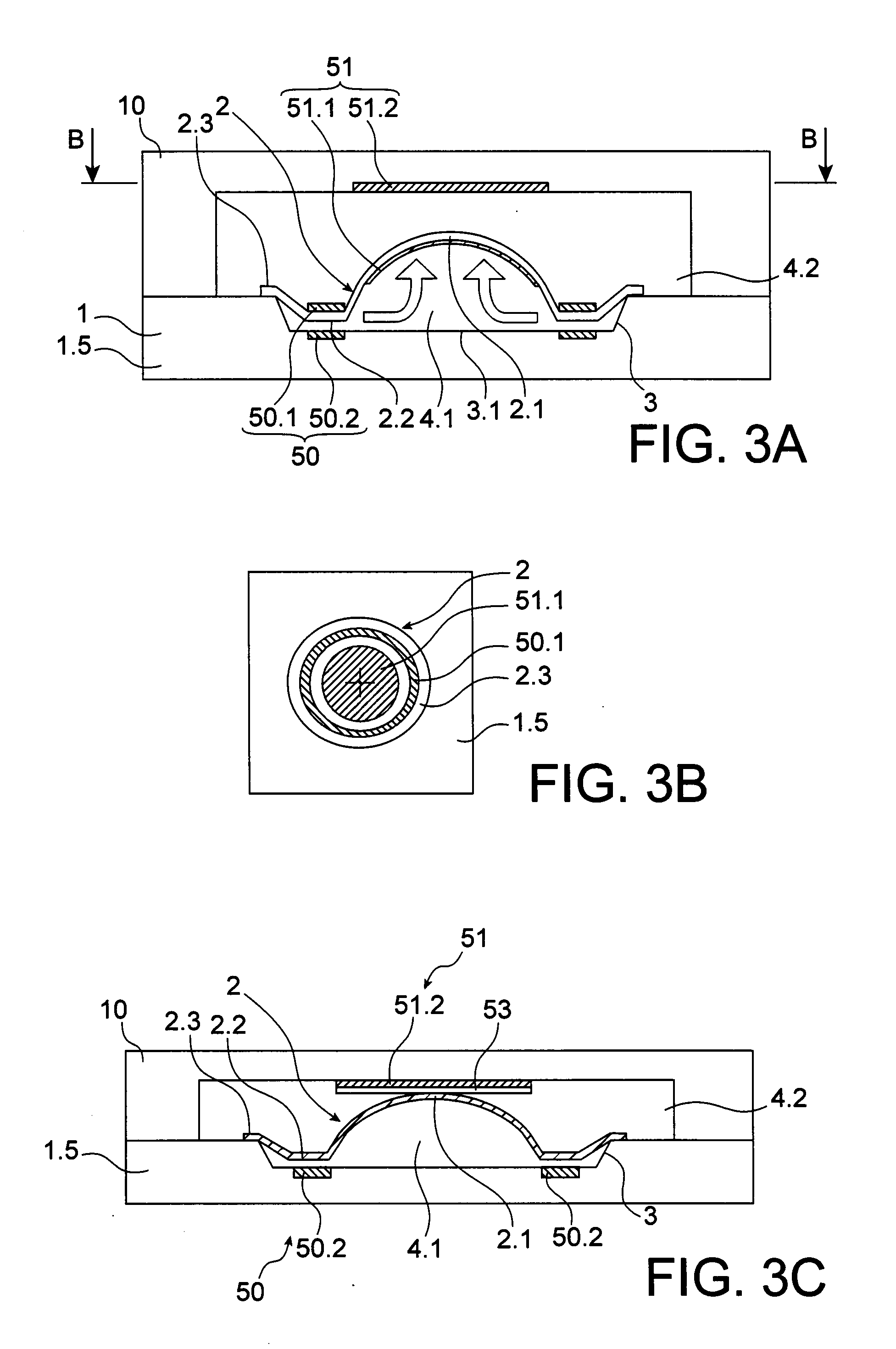
[0055]Reference should now be made to FIG. 1 which shows an optical device of the invention. It comprises at least one deformable membrane 2 of which the edge is anchored to a support 1.5.

[0056]The zone of the membrane 2 anchored to the support 1.5 is called anchoring zone and has the reference 2.3. In this example, the anchorage is made at the frame 1 of the support 1.5. The frame 1 contributes to bound a bowl 3 shaped in the support 1.5 and bordering it. The bowl 3 is intended to contain a constant volume of fluid 4.1 called first fluid located at least in the interior of the anchoring zone 2.3. If this first fluid is a gas, a slight compression of the gas may be allowed. The maximum permissible compression threshold corresponds to a value above which the substantially central zone 2.1 of the membrane is no longer deformed. It may obviously concern a liquid.

[0057]One of the faces of the membrane 2 is immersed in the first fluid 4.1. The support 1.5 extends along a main plane xoy. ...


PUM


Abstract

This relates to an optical device comprising at least one deformable membrane (2), a support (1.5), actuating means (50, 51) for loading the membrane (2) to deform it, the membrane (2) being provided with a zone (2.3) for anchoring to the support (1.5) and a substantially central zone (2.1) suitable for deforming reversibly surrounded by an anchoring zone (2.3), the support (1.5) and the membrane (2) contributing to imprison a constant volume located at least in the interior of the anchoring zone (2.3) of a fluid (4.1) called first fluid, in contact with one of the faces of the membrane (2). The actuating means (50, 51) of the membrane (2) comprise main actuating means (50) which load the membrane in a peripheral zone (2.2) lying between the central zone (2.1) and the anchoring zone (2.3) in order to move it in a direction and to move the first fluid (4.1) towards the central zone (2.1) and supplementary actuating means (51) anchored at least to the membrane which load the membrane (2) in the central zone (2.1) to move it in the reverse direction.

Description

TECHNICAL FIELD[0001]The present invention relates to a membrane deformable optical device enclosing a fluid and provided with membrane actuating means such as a variable focal length lens, an optical aberration correction lens in adaptive optics, or even a membrane deformable mirror.[0002]Liquid lenses are useful for example in mobile telephones having a still or video camera function. Many developments are under way, including in particular the autofocus function and the zoom function. During the introduction of these functions, an attempt is made to obtain the shortest possible response time. More generally, an attempt is made to integrate the maximum possible components of these miniature cameras to reduce the costs, size and power consumption. These miniature cameras, operating in the visible, are known as compact camera modules (CCM). They are commonly provided with lenses consisting of one or two liquids to which a voltage is applied to change their wettability.[0003]Another ...

Claims


Application Information

Patent Timeline
IPC IPC(8): G02B3/14G02B7/185
CPCG02B26/0825G02B3/14
Inventor BOLIS, SEBASTIEN
Owner WEBSTER CAPITAL LLC
Learn More