Microneedles, Microneedle Arrays, Methods for Making, and Transdermal and/or Intradermal Applications

a technology of microneedles and microneedle arrays, applied in the field of improving transdermal and/or intradermal drug delivery methods, can solve the problems of affecting the accuracy of the treatment, affecting the treatment effect, and destroying the separation of the masking material from the substrate, so as to reduce or even eliminate the pain associated, reduce the effect of pain and controllable drug delivery

Inactive Publication Date: 2010-05-13
MICROFAB
View PDF31 Cites 173 Cited by
  • Summary
  • Abstract
  • Description
  • Claims
  • Application Information

AI Technical Summary

Benefits of technology

[0057]It is an object of some embodiments of the invention to provide an improved method for providing shallow intradermal and / or transdermal (i.e. under 2 mm and preferably under 400 microns) injections of desired materials or drugs or extraction of fluids controllably from an array of micro-needles. These improved methods may involve, for example, the use of one or more of” (1) non-coring needles, (2) needles having diameters and tips that are small enough to substantially reduce or even eliminate pain associated with insertion, (3) needles that have a controllable and reliable insertion depth, (4) needle arrays that limit dispensing to that portion of the needles that have properly entered the target surface; (5) needle arrays that minimize drug delivery from needles that have not properly engaged the target surface; or (6) meet one of the other desirable features noted above in the background section of this application or meet another beneficial criteria that will be apparent to one of skill in the art upon review of the teachings herein.

Problems solved by technology

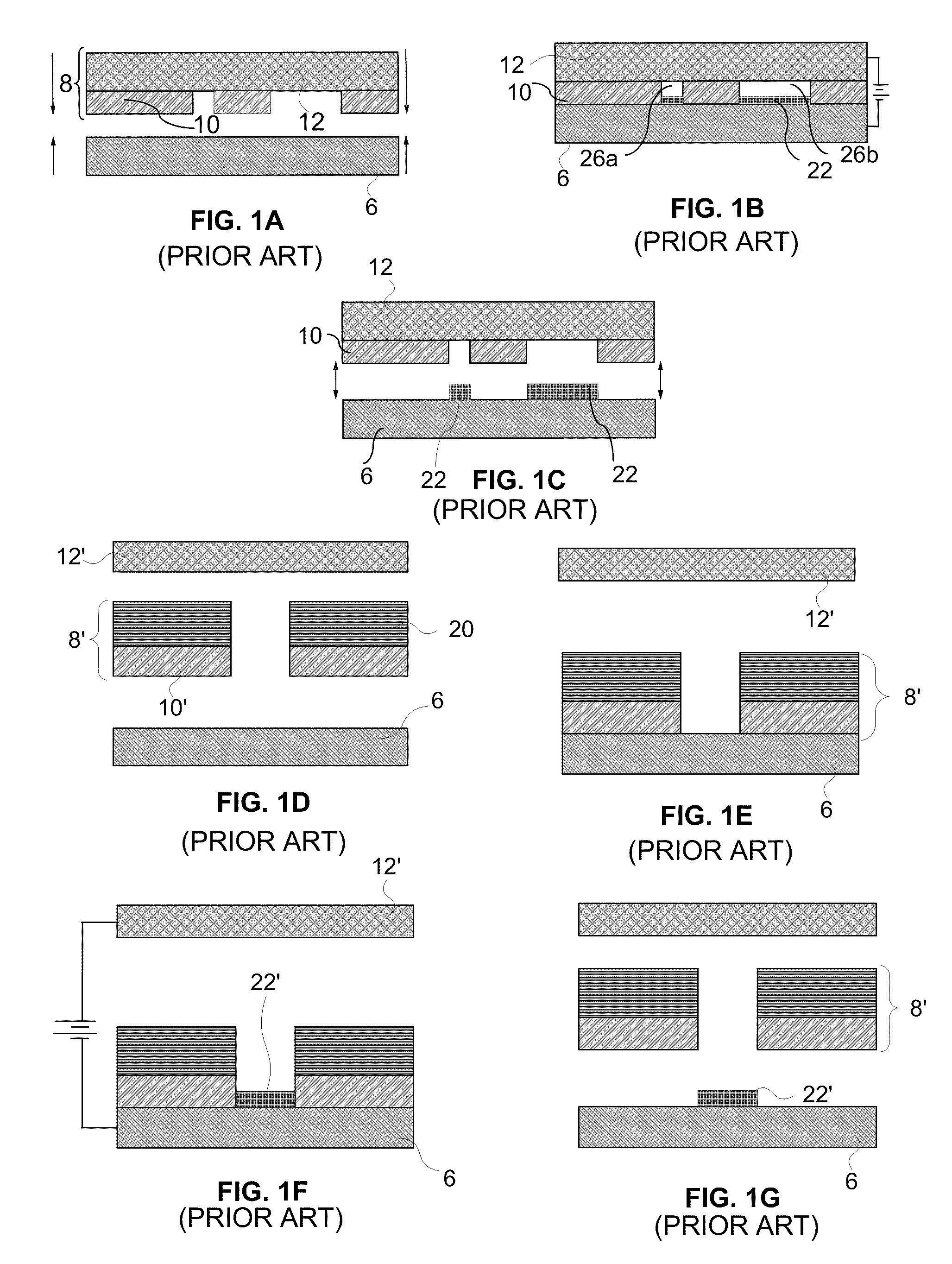
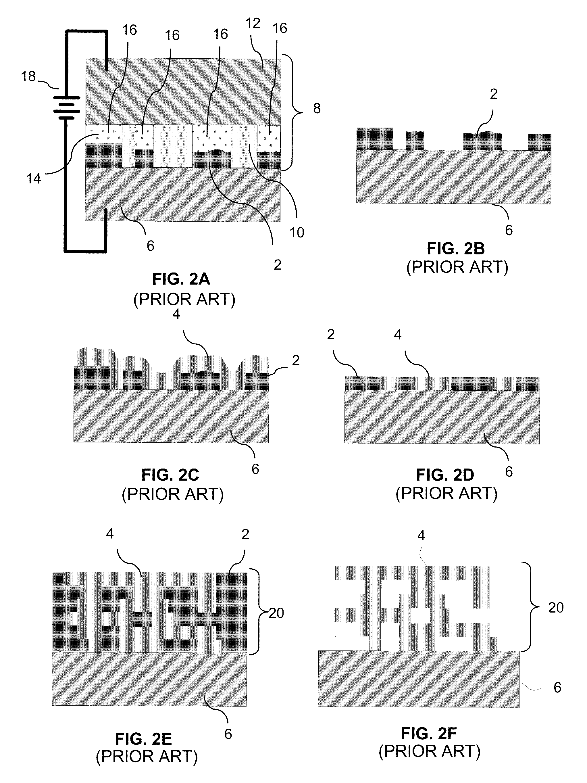
The CC mask plating process is distinct from a “through-mask” plating process in that in a through-mask plating process the separation of the masking material from the substrate would occur destructively.
In recent years, a number of researchers have attempted to develop hollow micro-needles and micro-needle arrays that could meet these requirements, but there have been many challenges.
However, it has been found that silicon's intrinsically high brittleness presents an absolute barrier to producing micro-needles that are safe (i.e. cannot shatter) inside the skin, leaving behind shards which can create irritation or infection, and making accurate dosing a challenge.
Silicon's brittleness alone virtually disqualifies it as a viable material for micro-needles.
Moreover, fabricating non-coring, pre-assembled / ready-to-use micro-needle arrays with low flow resistance requires fabricating relatively complex 3-D geometries: a difficult task using silicon.
Meanwhile, the Debiotech (Lausanne, Switzerland) silicon “Nanoject” needle does use a side port, but its fabrication process involves many costly steps).
Finally, silicon is a costly material with costly processing (e.g., deep reactive ion etching): well suited to making high-value computer chips but not so well suited to creating affordable alternatives to commodity products such as hypodermic needles.
In the case of polymers, strength, sharpness, geometrical limitations, and difficulties in sterilization have been issues, and in the case of glass, brittleness and geometrical limitations have prevented serious adoption.
However, the devices produced have been wanting, and the processes remain laboratory-scale and are not commercialized.
The simple geometries available have made the use of side ports for drug release impossible to achieve; thus all such devices release drug through a single port at the needle tip and are subject to tissue coring and plugging.
Moreover, the use of molds for these needles introduces some problems.
Silicon molds are costly to produce, a problem particularly if they are for a single use, while polymer molds (especially produced using laser machining) typically have rough, non-repeatable geometries and poor surface finishes.
However, the result is a needle of questionable sharpness (wall thickness is 10-20 μm) and with a single port at the tip which is subject to coring and plugging.
Alternative efforts (at Georgia Tech) to produce a metal needle with side ports have been somewhat successful, but are limited to making individual needles or 1-D (vs.
In the commercial realm, Becton, Dickinson and Company (Franklin Lakes, N.J.) appears to have a program to develop hollow metal micro-needles; these seem to be essentially miniaturized hypodermic needles, and an economical process for building arrays of these may be problematic.
Also, the needles may produce tissue coring.
Metals used for plated metal devices reported to date either have been of unacceptably low biocompatibility (e.g., pure nickel) or are potentially costly (e.g., palladium).

Method used


Image

  • Microneedles, Microneedle Arrays, Methods for Making, and Transdermal and/or Intradermal Applications
  • Microneedles, Microneedle Arrays, Methods for Making, and Transdermal and/or Intradermal Applications
  • Microneedles, Microneedle Arrays, Methods for Making, and Transdermal and/or Intradermal Applications

Examples


first example

Tapering Needle

[0199]FIGS. 11A-11C depict, respectively, a perspective view of a needle 1100, a cut view of the needle of showing internal passages, and an array formed from such needles for use in some examples. In some implementations of the example and its variations, the needles are formed from a multilayer, multi-material electrochemical fabrication process. To minimize the number of layers that must be formed and / or to minimize the impact that discrete layer steps will have on the structure as formed, the needles may be fabricated using a specific orientation. In the present example, the needles are formed with the stacking axis of the layers being the Z-axis while the planes of the layers are X-Y planes. To reduce stacking height, the longitudinal axis (i.e. the longest axis of a single needle, i.e. the Y-axis in the present example) may be oriented in the plane of the layers and to further minimize the stacking height of layers, the thinnest transverse direction (i.e. the Z-...

second example

Needle with Hips

[0208]FIGS. 12A-12D depict a needle 1200 and an array of needles such needles according to a second example of needles that may be used in some embodiments of the invention. The needle 1200 of the example of FIGS. 12A-12D includes an inlet hole 1220 (assuming material is to flow from the proximal end of the needle to the more distal outlets), two vertical outlet holes 1226, and two horizontal outlet holes 1222, and is also sharp at its distal tip or edge 1216. The needle features a bulged hip 1210 that tapers down in region 1206 to edge 1216. The hip 1210 is also defined by a maximum lateral extension that extends from the radial extent of the shaft or body portion 1204 of the needle via region 1208. The regions 1208 and 1206 may be considered to define an “arrowhead” (i.e. a portion of the needle that s positioned between the proximal and distal ends of the needle and that has a width that is greater than the width of an immediately proximal portion of the needle) w...

fourth example

Needles with Primary and Secondary Cutting Edges

[0223]In the fourth example of a needle implementation that may be used in some embodiments of the invention, each needle is provided with multiple cutting edges, some of which are staggered or recessed with respect to others. Such staggering may be applicable to micro-needles that are fabricated either horizontally or vertically. Cutting edges are obtained by designing individual layers with sharp points or by designing three-dimensional structures with thin blades which upon cross-sectioning produce layers with fine leading edge points (e.g. when the needle is fabricated horizontally, i.e., with the long axis of the needle parallel to the plane of the EFAB layers and with a tapering blade extending vertically through two or more layers). The needle of FIGS. 5-10 has a primary cutting edge that is sharp while secondary cutting edges are relatively rounded and dull.

[0224]FIG. 14A provides a perspective of a smooth walled CAD design of ...


PUM


Abstract

Embodiments are directed to microneedle array devices for intradermal and/or transdermal interaction with the body of patient to provide therapeutic, diagnostic or preventative treatment wherein portions of the devices may be formed by multi-layer, multi-material electrochemical fabrication methods and wherein individual microneedles may include valve elements or other elements for controlling interaction (e.g. fluid flow). In some embodiments needles are retractable and extendable from a surface of the device. In some embodiments, interaction occurs automatically with movement across the skin of the patient while in other embodiments interaction is controlled by an operator (e.g. doctor, nurse, technician, or patient).

Description

RELATED APPLICATIONS[0001]This application claims benefit of U.S. Patent Application Nos. 61 / 110,483 (MF Docket No. P-US234-A-MF) filed Oct. 31, 2008; 61 / 141,653 (P-US252-A-MF) filed Dec. 30, 2008; and 61 / 142,017 (P-US241-A-MF) filed Dec. 31, 2008; and this application is a continuation-in-part of U.S. patent application Ser. No. 12 / 197,969 P-US232-A-MF), filed Aug. 25, 2008 which in turn claims the benefit of U.S. Patent Application Nos. 61 / 078,750 (P-US192-D-MF) filed Jul. 7, 2008; 61 / 046,072 (P-US192-C-MF), filed Apr. 18, 2008; 61 / 046,000 (P-US192-B-MF), filed Apr. 18, 2008; and 60 / 968,026 (P-US192-A-MF) filed Aug. 24, 2007. Each of these applications is incorporated herein by reference as if set forth in full herein.FIELD OF THE INVENTION[0002]Embodiments of the invention relate to improved transdermal and / or intradermal drug delivery methods and systems with some embodiments directed to broad area, shallow depth, multi-needle, transdermal and / or intradermal delivery systems. So...

Claims


Application Information

Patent Timeline
Patent Type & Authority Applications(United States)
IPC IPC(8): A61M5/32
CPCA61M37/0015A61M2037/0023A61M2037/0053A61M2037/0046A61M2037/003
Inventor LOCKARD, MICHAEL S.ARAT, VACITCOHEN, ADAM L.NIELSEN, KIRK G.
Owner MICROFAB
Why Eureka
Try Eureka