
Auto-calibration of orientation sensing systems

a technology of orientation sensing and automatic calibration, which is applied in the direction of speed/acceleration/shock measurement devices, instruments, surveying and navigation, etc., can solve the problems of not being able to apply the known approach to configurations using a 2d magnetometer and/or a 2d accelerometer, and the combination of a 3d magnetometer is limited. to achieve the effect of improving accuracy and improving accuracy

Inactive Publication Date: 2010-05-13
NXP BV
View PDF8 Cites 88 Cited by
  • Summary
  • Abstract
  • Description
  • Claims
  • Application Information

AI Technical Summary

Benefits of technology

[0011]In an embodiment of the invention, each of the first quantities is an average of multiple first vectors supplied by the first sensor. This averaging cancels out the effects of vibrations, thus improving accuracy.
[0012]In a further embodiment, each of the second quantities is an average of multiple second vectors supplied by the second sensor. This averaging similarly cancels out effects of vibrations and thus improves accuracy.
[0014]Accordingly, the creation of averages of the first and / or second vectors is discontinued as soon as the first sensor or the second sensor supplies a sample that deviates from the running average, built up so far, by more than a certain distance. If the average has been created from less than a certain minimum number of samples, the average will be discarded. This approach reduces the influence, on the integrity of the collected data, of dynamic orientation changes and mechanical vibrations.
[0020]In still another embodiment, the first sensor comprises a 2D magnetometer; and the second sensor comprises a 3D accelerometer. This configuration has been discussed briefly above. Its attractiveness lies in the low cost-implementation.

Problems solved by technology

The known technique is limited to the combination of a 3D magnetometer and a 3D accelerometer.
It cannot be used in the case where one or both sensors are only 2D.
The known approach therefore cannot be applied to configurations using a 2D magnetometer and / or a 2D accelerometer.

Method used


Image

  • Auto-calibration of orientation sensing systems
  • Auto-calibration of orientation sensing systems
  • Auto-calibration of orientation sensing systems

Examples


Embodiment Construction

[0028]The magnetometer in an electronic compass serves to measure the components of the earth-magnetic field vector. However, ferrous materials in the neighborhood of the magnetometer affect the magnetic field as measured by the magnetometer. If it is not known how these materials affect the measurement from the magnetometer, the orientation or heading angle output of the compass will be inaccurate. Calibration is needed to compensate for the effects of ferrous materials on the measured field, so as to maintain accuracy.

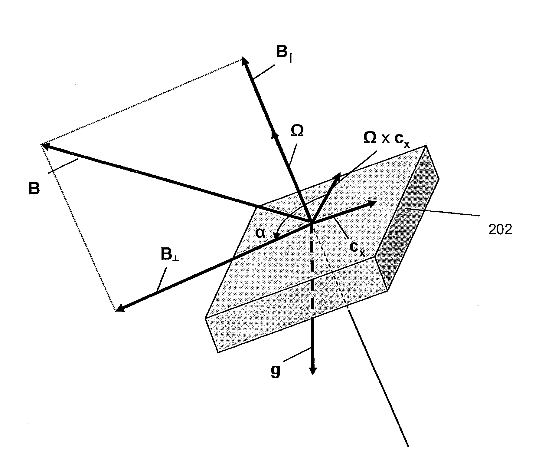
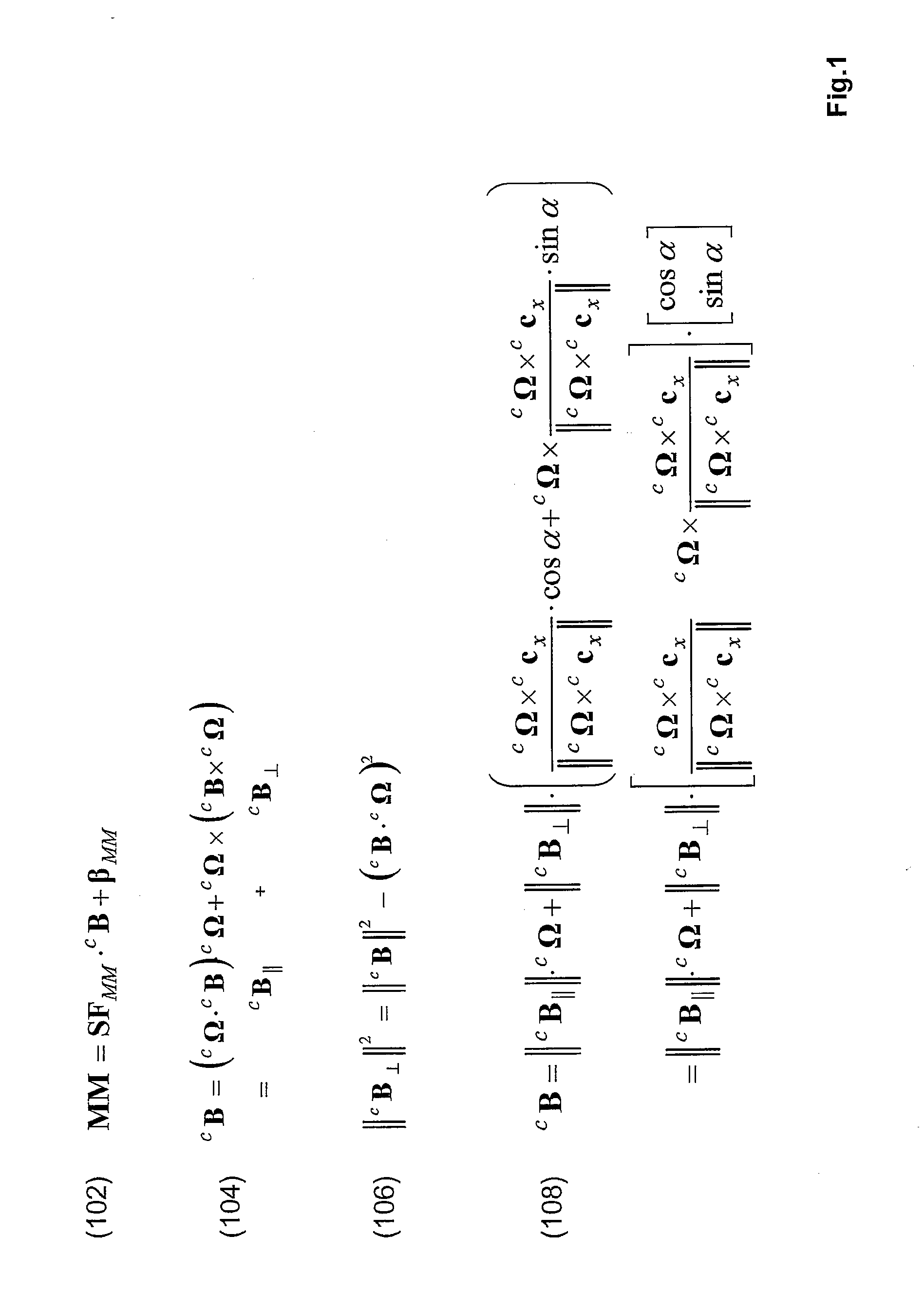
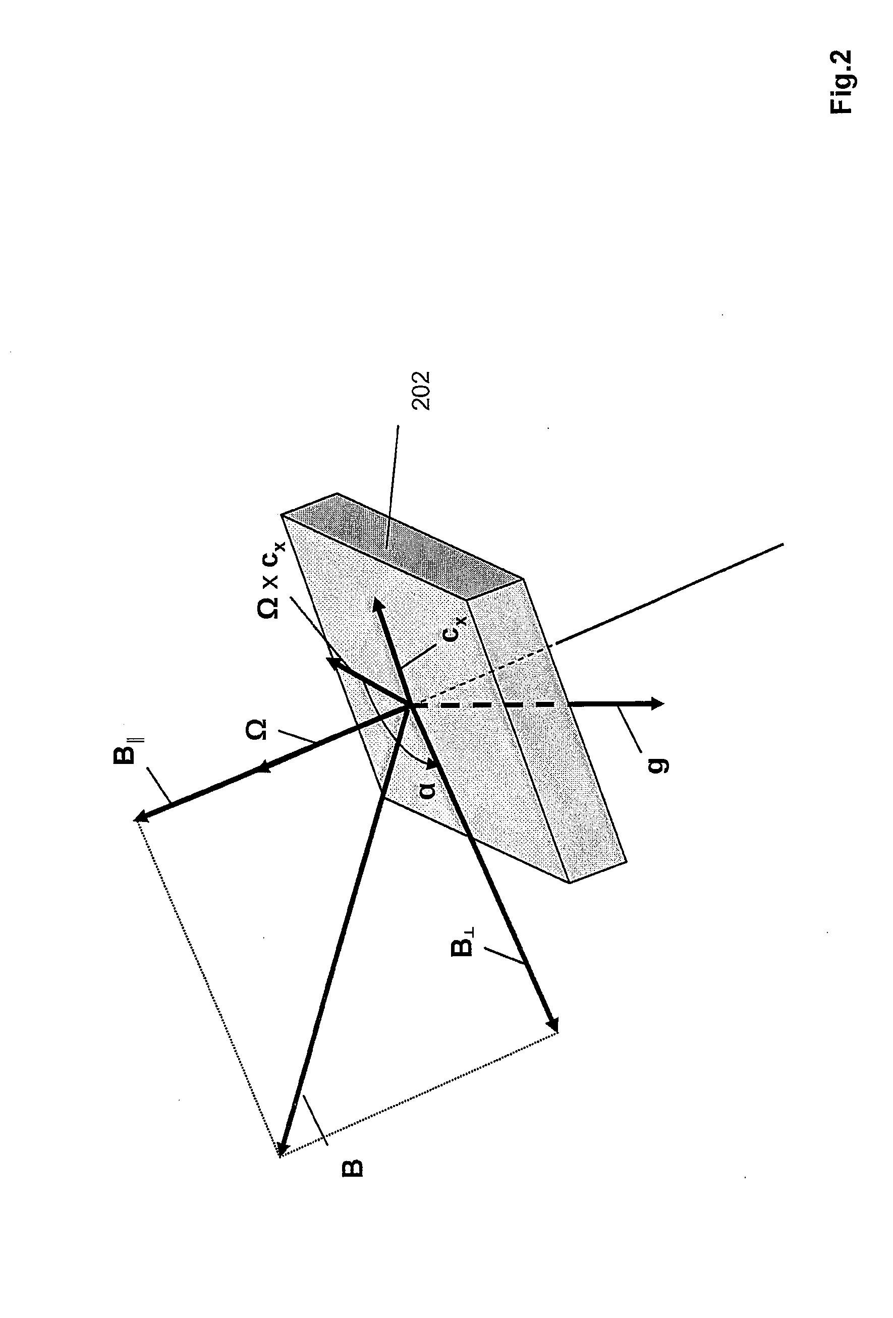
[0029]The magnetometer supplies an output signal vector MM, which is a three-dimensional (3D) vector for a 3D magnetometer, or a 2D (two-dimensional) vector for a 2D magnetometer. Vector MM is related to the 3D earth-magnetic field vector cB referenced with respect to a coordinate system fixed to the compass. The superscript “c” stands for “corpus” (Latin for “body”). An expression for vector MM is given by linear matrix equation (102) in FIG. 1. The quantity SFMM is...


PUM


Abstract

An electronic device has an orientation sensing system for determining an orientation of the device. The system comprises a magnetometer and an accelero meter. The system further has calibration means to calibrate the sensing system for operational use. The accelerometer supplies measurements used to constrain a range of possible directions of the external magnetic field to be determined. The calibration means numerically solves a set of equations and is equally well useable for a 2D or 3D magnetometer in combination with a 2D or 3D accelerometer.

Description

FIELD OF THE INVENTION[0001]The invention relates to an electronic device that has an orientation sensing system that comprises a first sensor for sensing acceleration and a second sensor for sensing a magnetic field. The orientation sensing system comprises a calibration system. The device is, for example, an electronic mobile device such as a mobile telephone, a palmtop PC or personal digital assistant, or a stand-alone electronic navigation device for a land vehicle, a boat or an airplane, etc. The invention also relates to a method of calibrating such a system and to software for carrying out this method on a microprocessor.BACKGROUND ART[0002]Compass magnetometers are calibrated in order to compensate for offsets, scale factor deviations, alignment tolerances and the influence of magnetic materials. The compensation reduces errors in the calculated orientation of the device. The aforementioned effects, and in particular the influence of magnetic materials, may change over time....

Claims


Application Information

Patent Timeline
IPC IPC(8): G01C17/38G06F19/00
CPCG01C17/38
Inventor BOEVE, HANS MARC BERTIKKINK, TEUNIS JANDURIC, HARIS
Owner NXP BV
Learn More