Debugging system, debugging method, debugging control method, and debugging control program

a debugging system and control method technology, applied in the field of debugging system, can solve the problems of unnecessary error detection and unnecessary error detection, and achieve the effect of suppressing unnecessary error detection

Inactive Publication Date: 2010-05-13
RENESAS ELECTRONICS CORP
View PDF7 Cites 13 Cited by
  • Summary
  • Abstract
  • Description
  • Claims
  • Application Information

AI Technical Summary

Benefits of technology

[0015]Consequently, even when debugging is performed only on a particular processor in the redundant processor system, the comparison between the outputs from the processors is suppressed, and thus unnecessary error detection can be suppressed.
[0016]According to an exemplary embodiment of the present invention, it is possible to provide a debugging system, a debugging method, a debugging control method, and a debugging control program that are capable of suppressing unnecessary error detection.

Problems solved by technology

This results in a problem that an error indicating a mismatch between the operation results from the two processors is detected.
In other words, since the two processors execute the same instruction and it is determined whether the operation results thereof match, unless the DCU has a redundant configuration similar to that of the processor, the following problem is caused.
That is, when a break occurs in the debug processing, for example, the operation of the processor having the DCU mounted therein is stopped, while the other processor continues operation, which causes a mismatch between the operation results.
As a result, unnecessary error detection is carried out.
The present inventor has found a problem that, as described in the background section, when debugging is performed only on a particular processor in the redundant processor system, there is a problem that unnecessary error detection is carried out.

Method used


Image

  • Debugging system, debugging method, debugging control method, and debugging control program
  • Debugging system, debugging method, debugging control method, and debugging control program
  • Debugging system, debugging method, debugging control method, and debugging control program

Examples


first exemplary embodiment

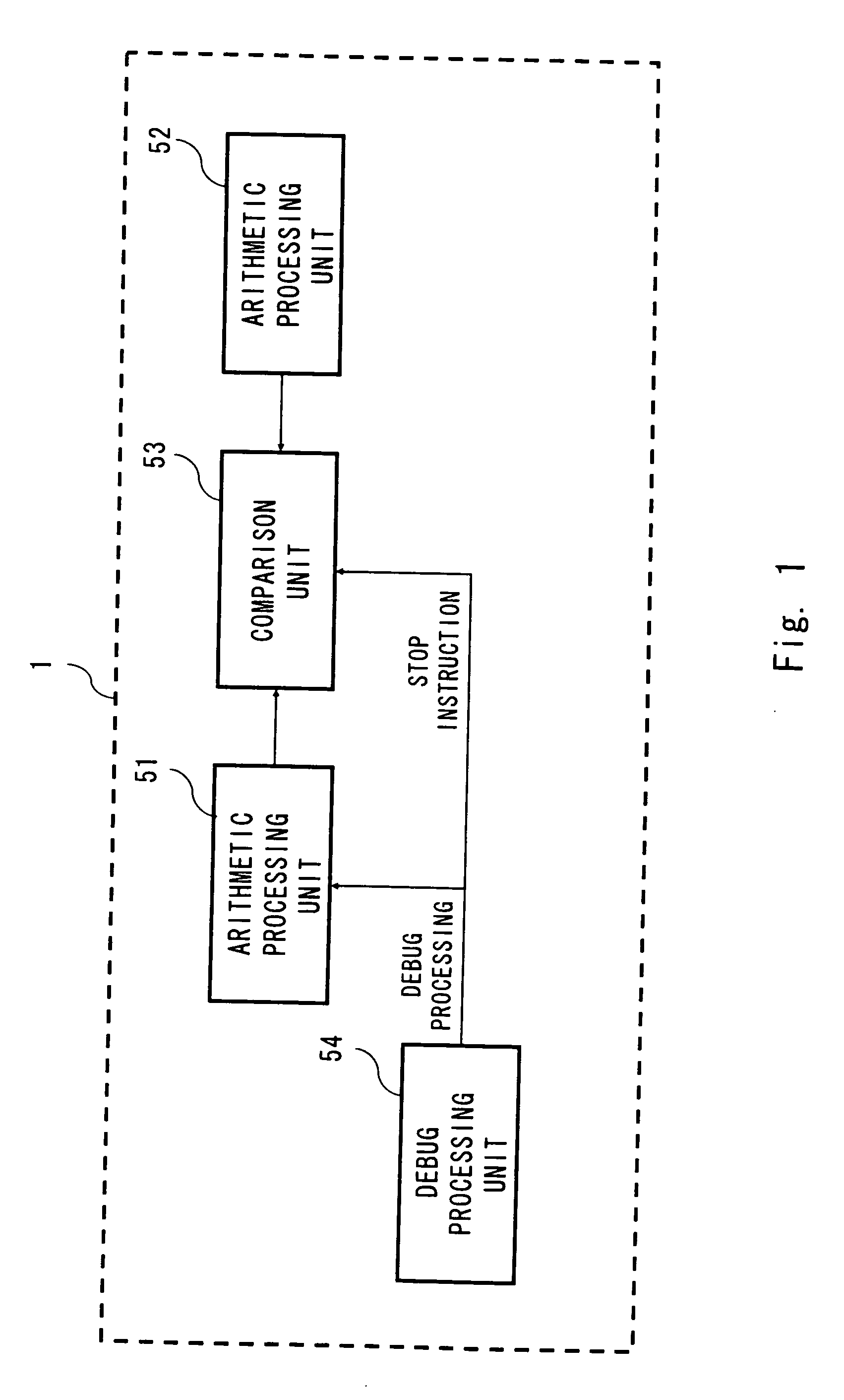
[0025]FIG. 1 is a block diagram schematically showing a debugging system according to a first exemplary embodiment of the present invention.

[0026]A debugging system 1 includes arithmetic processing units 51 and 52, a comparison unit 53, and a debug processing unit 54. The following description is made assuming that debugging is performed on arithmetic processing executed by the arithmetic processing unit 51.

[0027]Each of the arithmetic processing units 51 and 52 is composed of a device capable of performing arithmetic processing, such as a processor. Examples of the processor herein described include a physical processor which is formed on another chip, such as a central processing unit (CPU), and a logic processor which is formed on the same chip, such as a CPU core.

[0028]The comparison unit 53 compares an output from the arithmetic processing unit 51 with an output from the arithmetic processing unit 52, and detects a mismatch between the outputs as an error.

[0029]The debug proces...

second exemplary embodiment

[0051]FIG. 4 is a block diagram showing a debugging system according to a second exemplary embodiment of the present invention.

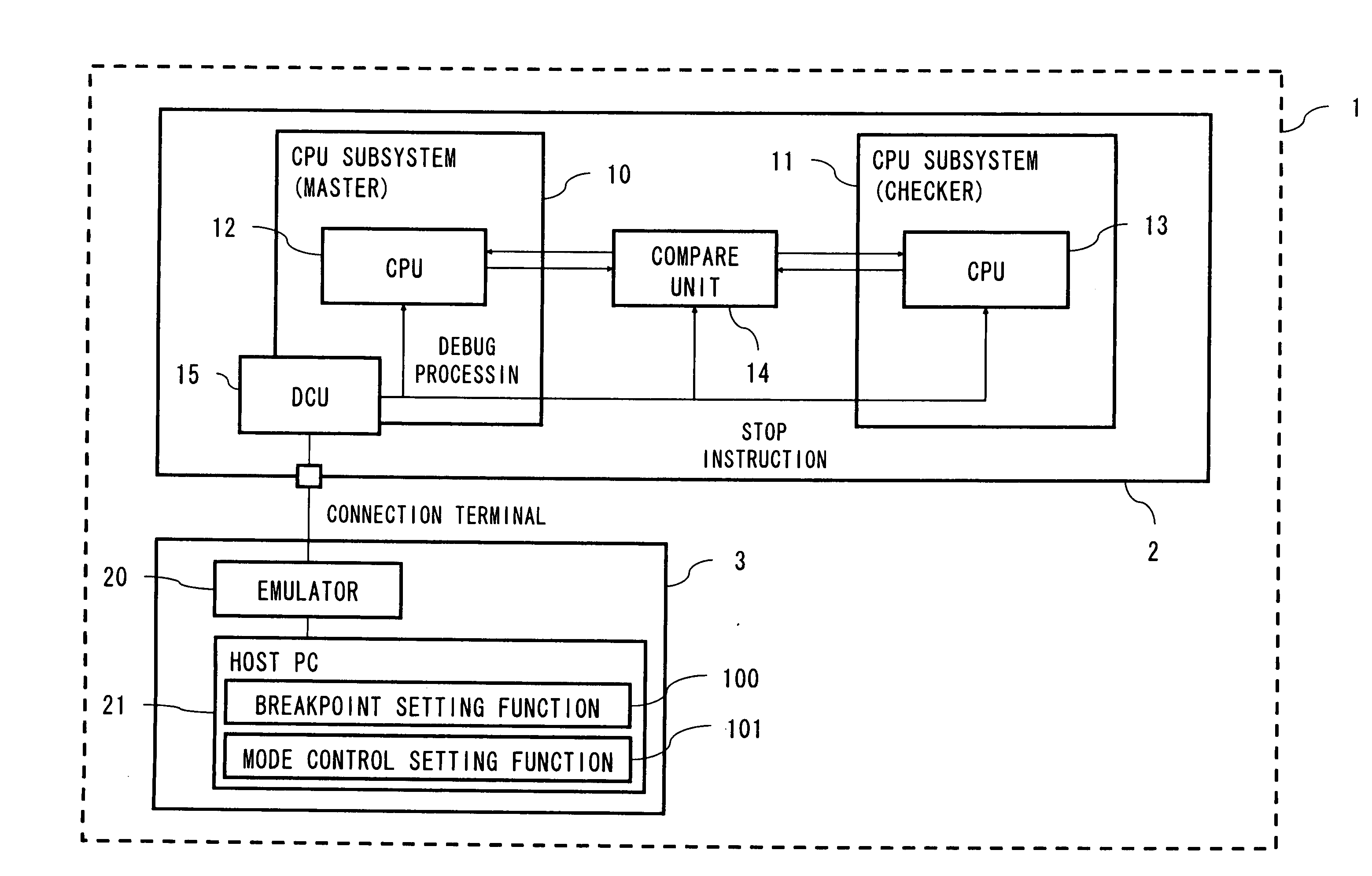
[0052]Note that the constituent elements shown in FIG. 4 are similar to those of the first exemplary embodiment, so the description thereof is omitted. This exemplary embodiment differs from the first exemplary embodiment shown in FIG. 2 in that a breakpoint setting function 100 and a mode control setting function 101 are described in detail as functions of the host PC 21.

[0053]The breakpoint setting function 10 is a function for setting a breakpoint in a program to be executed by the redundant processor system.

[0054]The mode control setting function 101 determines a timing for outputting a stop instruction to each of the compare unit 14 and the CPU subsystem 11 from the DCU 15, based on the breakpoint set by the breakpoint setting function 10.

[0055]Referring next to the flowchart of FIG. 5, the operation of the debugging system according to the second exemp...

third exemplary embodiment

[0066]Referring now to the flowchart of FIG. 6, the operation of a debugging system according to a third exemplary embodiment of the present invention will be described.

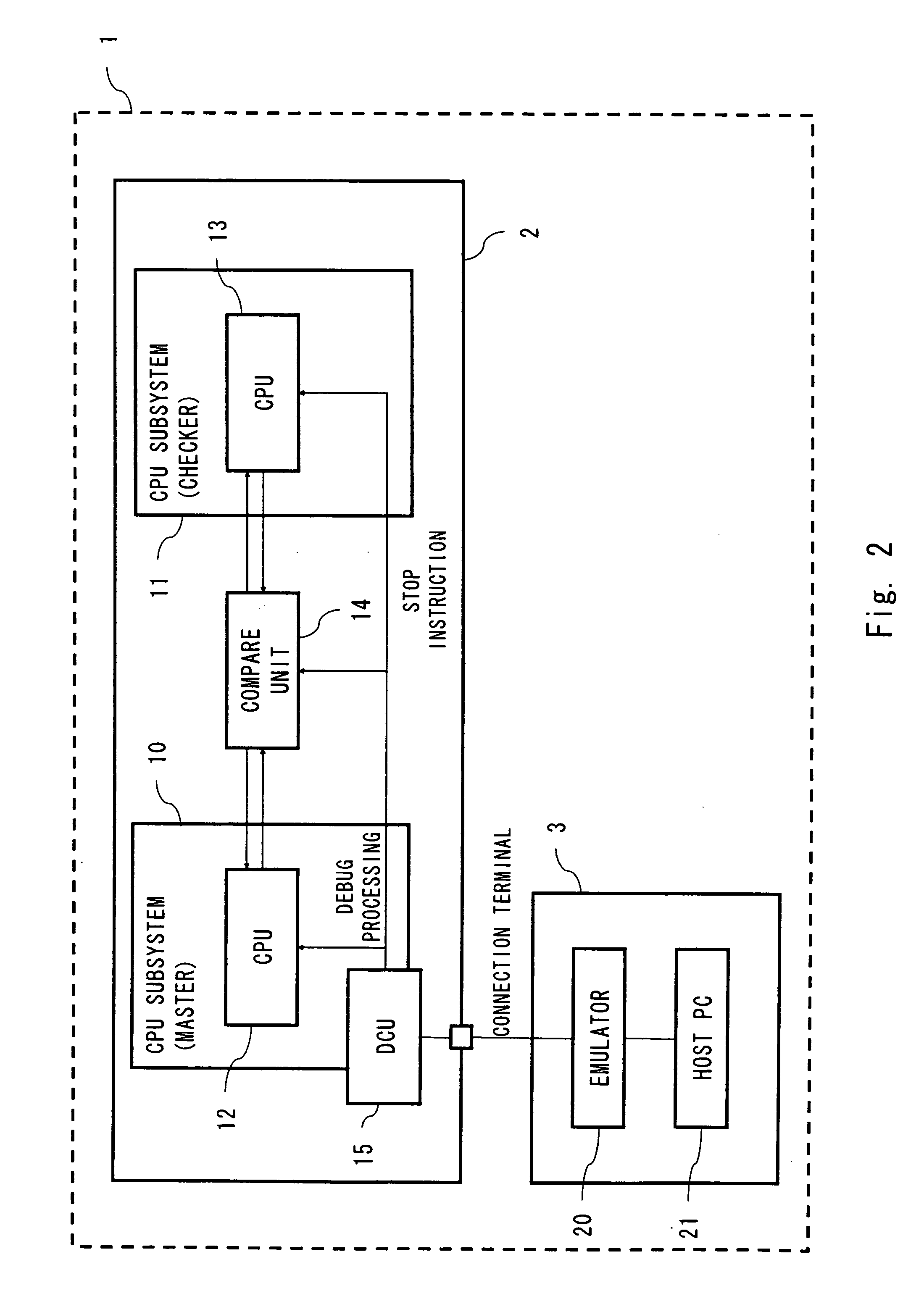
[0067]Note that the overall configuration of the debugging system according to the third exemplary embodiment of the present invention is similar to that shown in FIG. 2, so the description thereof is omitted.

[0068]First, the debugging control system 3 is connected to the DCU 15 to activate the debugger in the host PC 21 (S501).

[0069]At the timing when the debugger is activated, the stop instruction is output from the host PC 21 to each of the CPU subsystem 11 and the compare unit 14 through the emulator 20 and the DCU 15 (S502). As a result, the operations of the CPU 13 and the compare unit 14 are stopped.

[0070]After the operations of the CPU 13 and the compare unit 14 are stopped, the debug processing for the CPU 12 is started (S304).

[0071]As described above, according to this exemplary embodiment, even when debugg...


PUM


Abstract

A debugging system according to an exemplary embodiment of the present invention includes: a plurality of arithmetic processing units (51, 52) that perform arithmetic processing; a comparison unit (53) that compares outputs from the plurality of arithmetic processing units (51, 52); and a debug processing unit (54) that outputs a stop instruction for stopping operation of the comparison unit (53), to the comparison unit 53, when debug processing is performed on a predetermined arithmetic processing unit among the plurality of arithmetic processing units (51, 52).

Description

BACKGROUND[0001]1. Field of the Invention[0002]The present invention relates to a debugging system, a debugging method, a debugging control method, and a debugging control program.[0003]2. Description of Related Art[0004]In recent years, there is a demand for adopting a redundant processor, which is composed of a plurality of processors, in an on-vehicle microcomputer for a chassis system related to safety features such as a brake. In a redundant processor system, processors are caused to execute the same instruction, and operation results from the processors are compared with each other to enable detection of a failure of the processors, for example, thereby achieving an improvement in safety. In this case, it is necessary to implement a debug function without impairing operational safety when a redundant function is enabled.[0005]A processor having the debug function can be achieved by mounting a unit having the debug function in the processor. The unit having the debug function i...

Claims


Application Information

Patent Timeline
Patent Type & Authority Applications(United States)
IPC IPC(8): G06F9/30
CPCG06F11/3664G06F11/1641
Inventor YARIMIZU, HIROKI
Owner RENESAS ELECTRONICS CORP
Why Eureka
Try Eureka