Method and apparatus for forming bend-controlling straps in sheet material

a technology of bend control and sheet material, which is applied in the direction of shaping tools, forging/pressing/hammering apparatus, forging/hammering/pressing machines, etc., can solve the problems of reducing the precision of tool press fabrication, reducing the cost of process, and reducing the tonnage.

Inactive Publication Date: 2010-05-20
IND ORIGAMI INC CA US
View PDF95 Cites 28 Cited by
  • Summary
  • Abstract
  • Description
  • Claims
  • Application Information

AI Technical Summary

Benefits of technology

[0016]At least one of the punch block and the die block may be formed of a plurality of modular chips, each chip being substantially square-shaped and having a shear edge extending along each side thereof. A portion of the plurality of modular chips may be identical, each identical modular chip including a centrally located indentation forming a respective recess of the die block. A portion of the plurality of

Problems solved by technology

While such sheet materials can be formed using laser cutting or water jet cutting processes, such processes are typically relatively expensive.
The punch and die sets of such tooling are often formed of hardened steel or other hardened metals that are relatively expensive to fabricate.
The precision of the tool press fabrication decreases due to the number of discrete hits which leads to punched parts of lesser quality.
Dull punches

Method used


Image

  • Method and apparatus for forming bend-controlling straps in sheet material
  • Method and apparatus for forming bend-controlling straps in sheet material
  • Method and apparatus for forming bend-controlling straps in sheet material

Examples


Embodiment Construction

[0033]Reference will now be made in detail to various embodiments of the present invention(s), examples of which are illustrated in the accompanying drawings and described below. While the invention(s) will be described in conjunction with exemplary embodiments, it will be understood that present description is not intended to limit the invention(s) to those exemplary embodiments. On the contrary, the invention(s) is / are intended to cover not only the exemplary embodiments, but also various alternatives, modifications, equivalents and other embodiments, which may be included within the spirit and scope of the invention as defined by the appended claims.

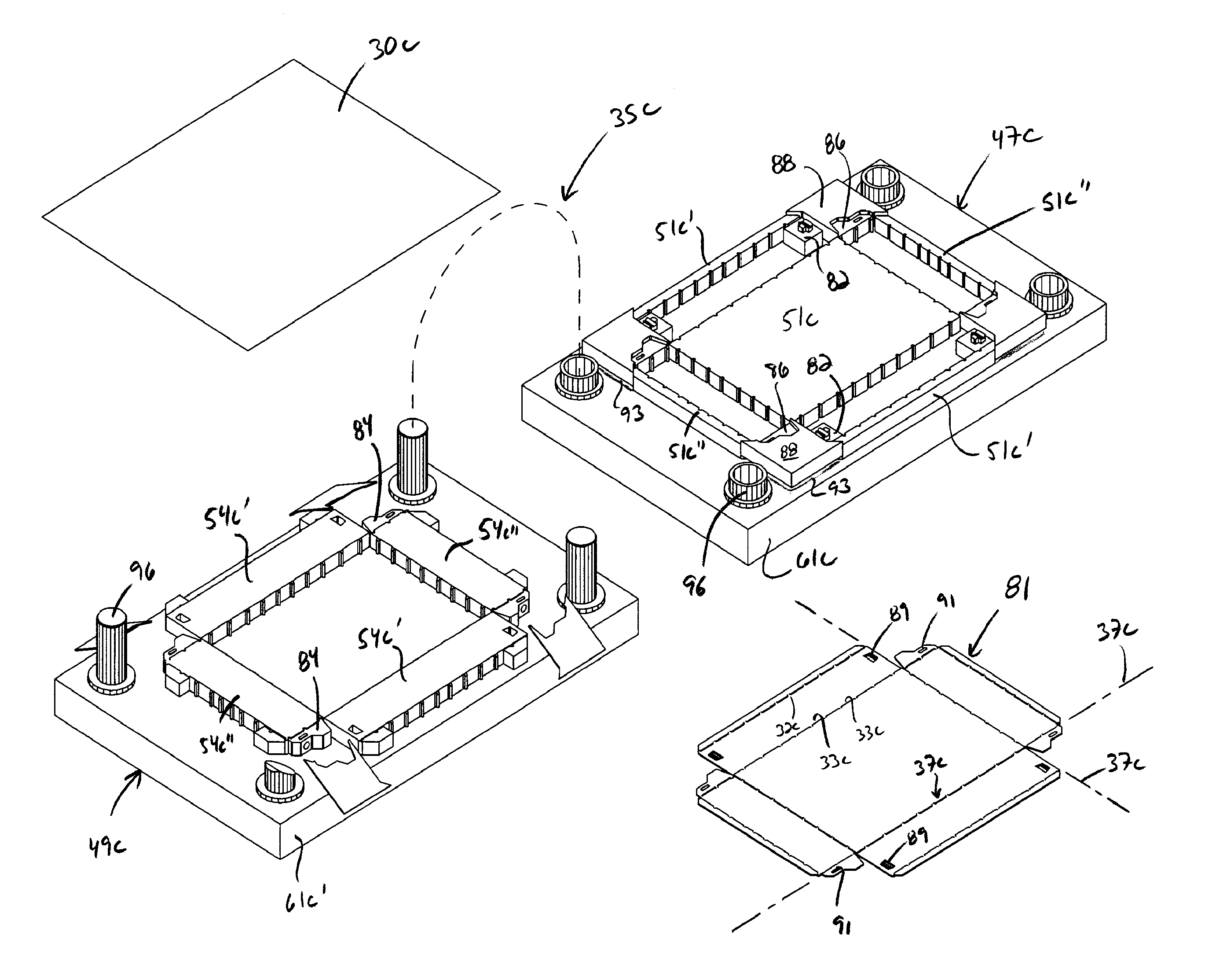
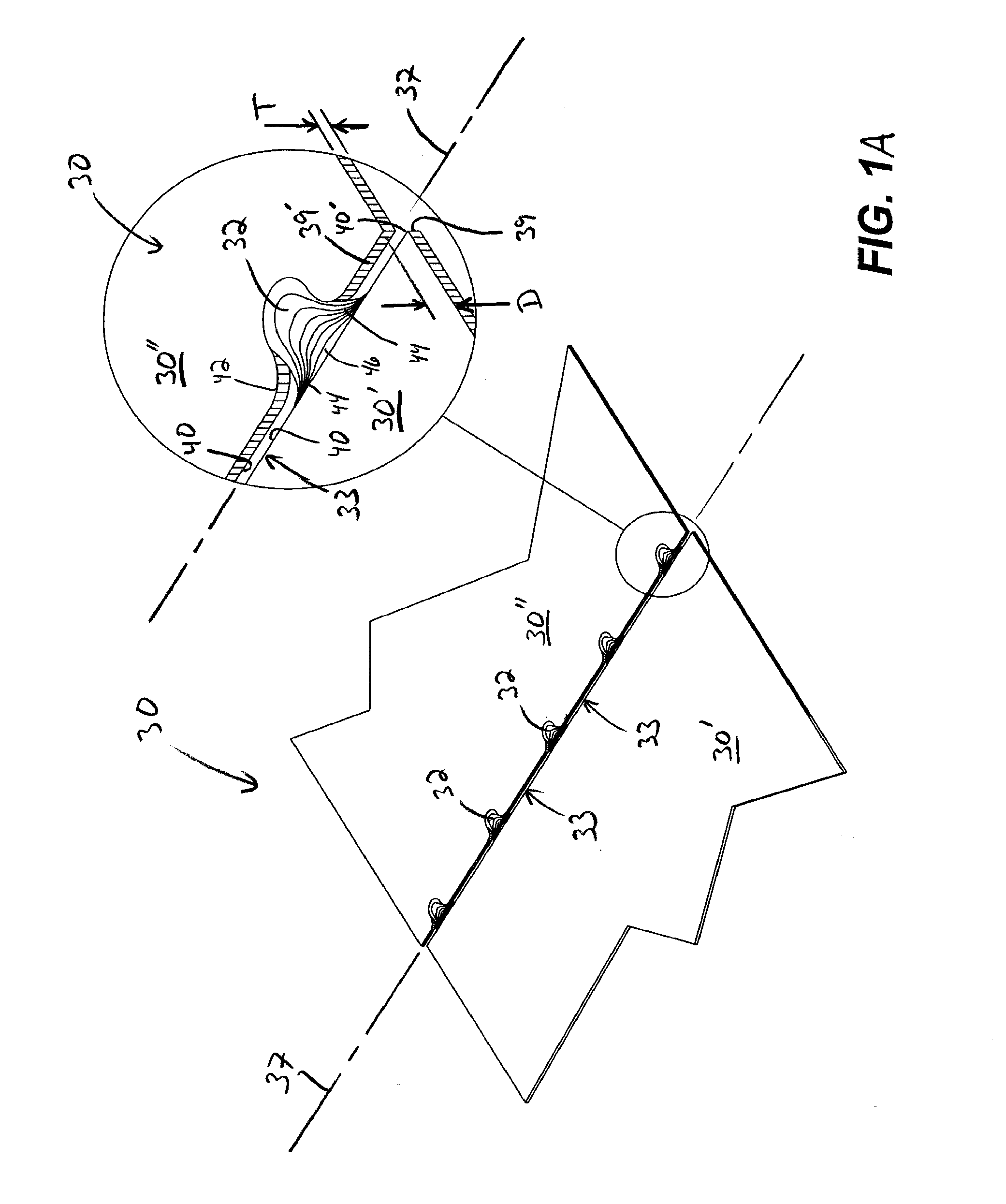
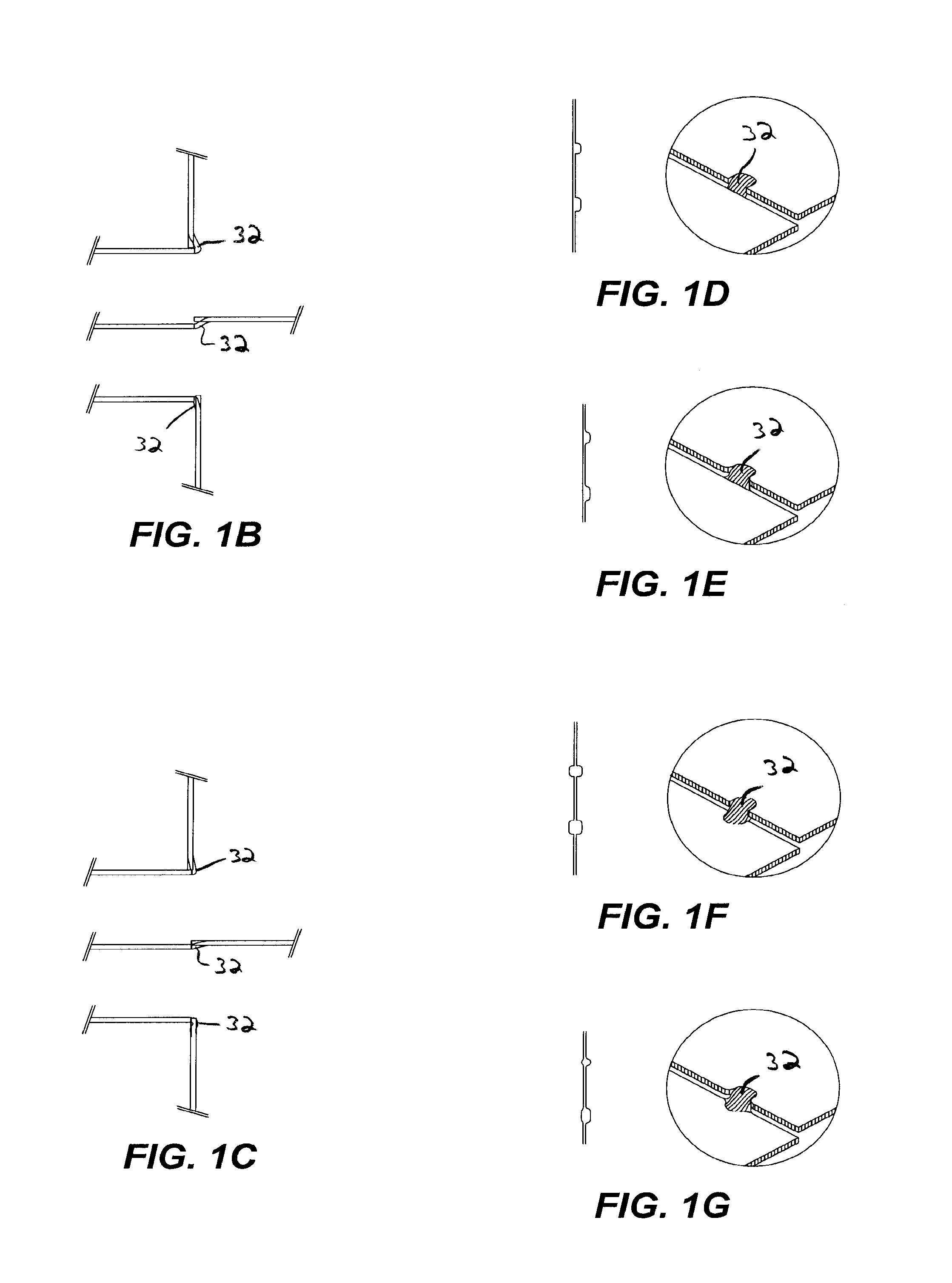
[0034]Turning now to the drawings, wherein like components are designated by like reference numerals throughout the various figures, attention is directed to FIG. 1A which illustrates an exemplary substantially two-dimensional (2D) sheet material work piece 30 having bend-controlling straps 32 formed by interrupted lengths of shear or...


PUM

PropertyMeasurementUnit
Fractionaaaaaaaaaa
Angleaaaaaaaaaa
Lengthaaaaaaaaaa

Abstract

A substantially two-dimensional sheet material is configured for bending along a bend line to form a three-dimensional article. The sheet material includes a sheet of elastically and plastically deformable material, one portion of the sheet material located on one side of the bend line and another portion located on the opposing side of the bend line, one portion being displaced relative to the another portion in the direction of the thickness of the sheet material, and/or a plurality of shear lengths extending along the bend line separating the one and another portions of the sheet material. At least a pair of adjacent shear lengths define a strap interconnecting the one and another portions of the sheet material. A tooling assembly is configured for forming the bend-controlling straps and includes a punch assembly and a die assembly dimensioned and configured to move relative to one another, a punch block having a continuous shear edge, the punch block removably secured on the punch assembly, and/or a die block having an interrupted shear edge broken into shear edge segments by one or more recesses, the die block removably mounted on the die assembly, wherein moving one of the punch assembly and the die assembly toward the other, the continuous shear edge of the punch block cooperates with the shear edge segments for impart shear lengths upon the sheet material along the predetermined bend line. A method of using the tooling assembly and forming the sheet material is also described.

Description

CROSS-REFERENCES TO RELATED APPLICATIONS[0001]This application claims priority to U.S. Provisional Patent Application No. 61 / 115,095 filed Nov. 16, 2008, entitled METHOD AND APPARATUS FOR FORMING BEND-CONTROLLING STRAPS IN SHEET MATERIAL, the entire contents of which is incorporated herein for all purposes by this reference.BACKGROUND OF THE INVENTION[0002]1. Field of the Invention[0003]This invention relates, in general, to methods and apparatus for forming bend-controlling straps in sheet materials.[0004]2. Description of Related Art[0005]Various techniques or manufacturing processes for forming slits, grooves, displacements and other means in a wide variety of sheet materials that precisely control bending of the sheet materials are known. Such means include laser cutting, water jet cutting, stamping, punching, molding, casting, stereo lithography, roll forming, machining, chemical-milling, photo-etching and the like. Such means may be applied to numerous structures which are for...

Claims


Application Information

Patent Timeline
IPC IPC(8): B21D37/10B21D31/02B29B7/00B32B3/00
CPCB21D11/08Y10T428/24479B21D37/10B21D28/10
Inventor DURNEY, MAX W.
Owner IND ORIGAMI INC CA US
Why Eureka
Try Eureka