

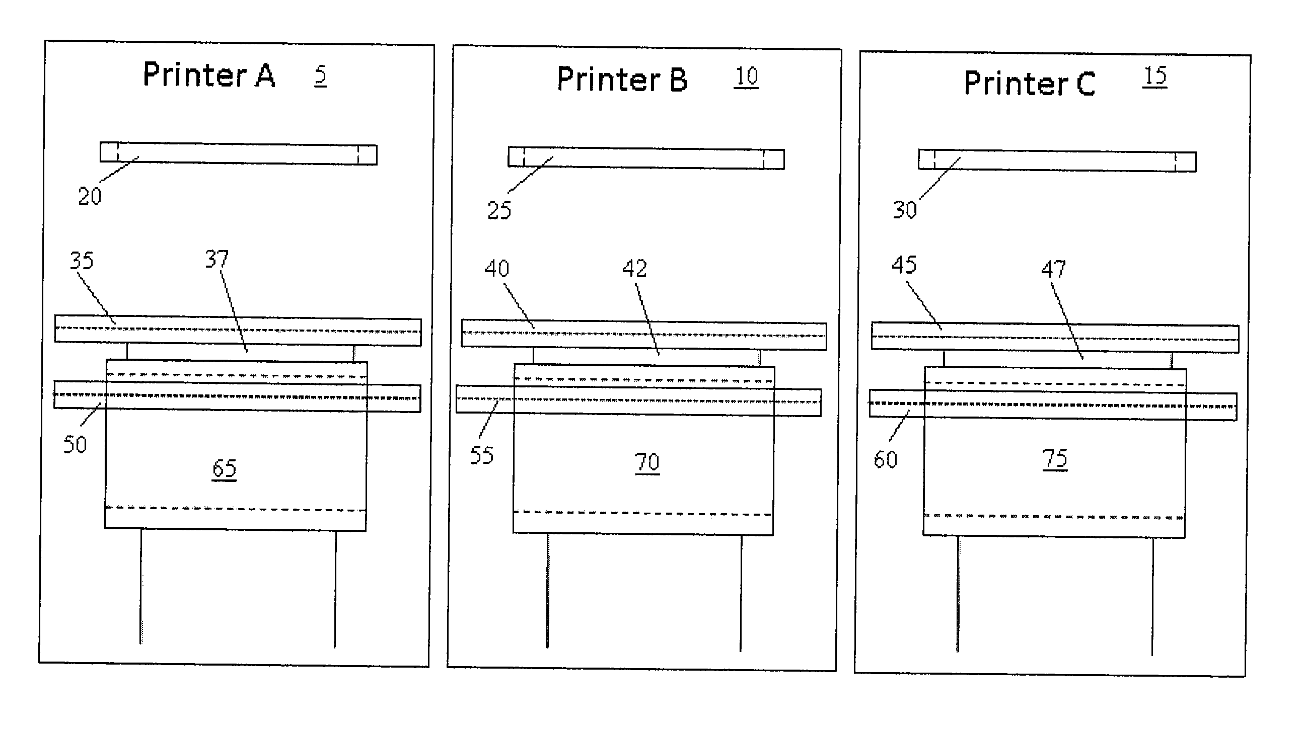
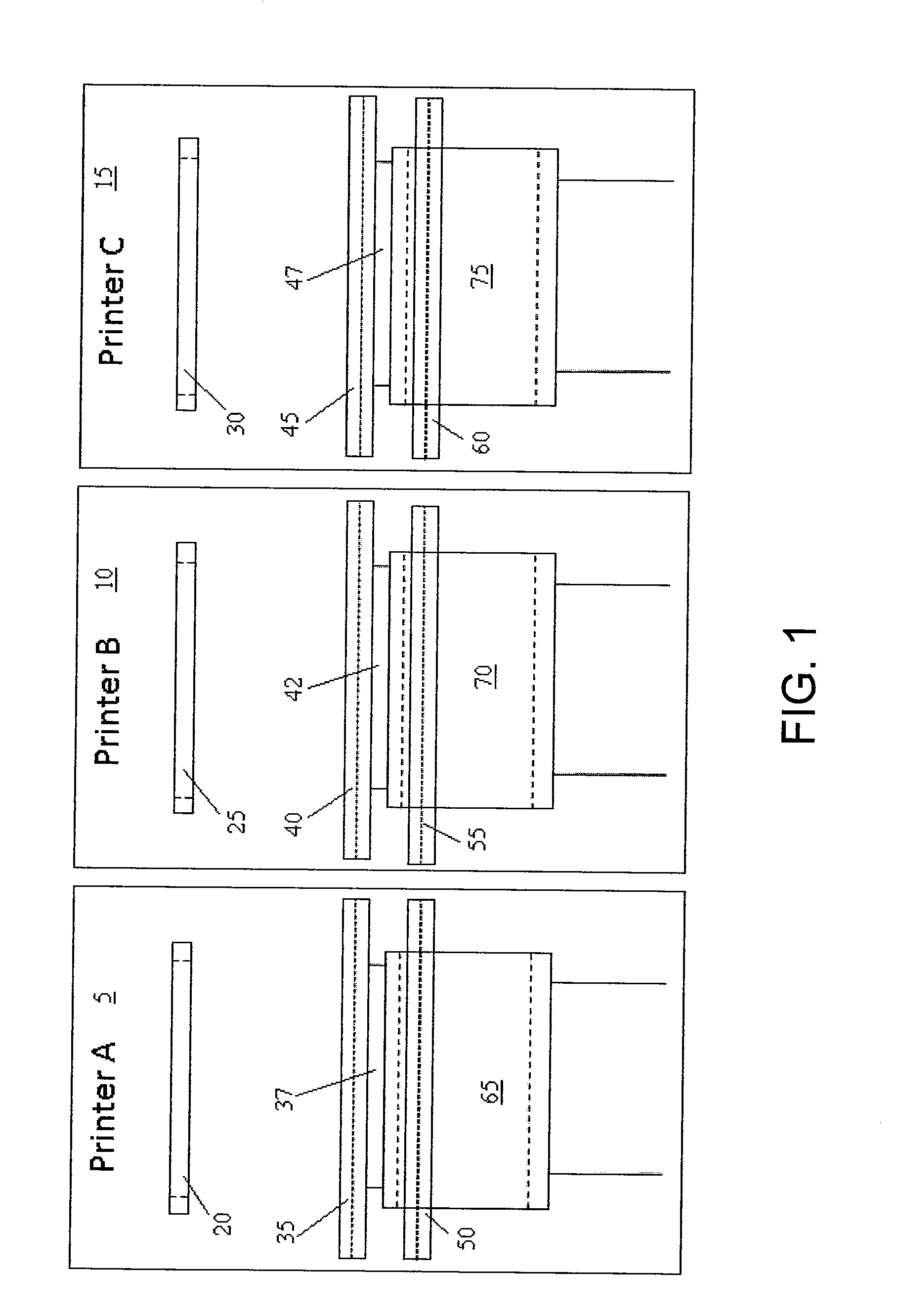
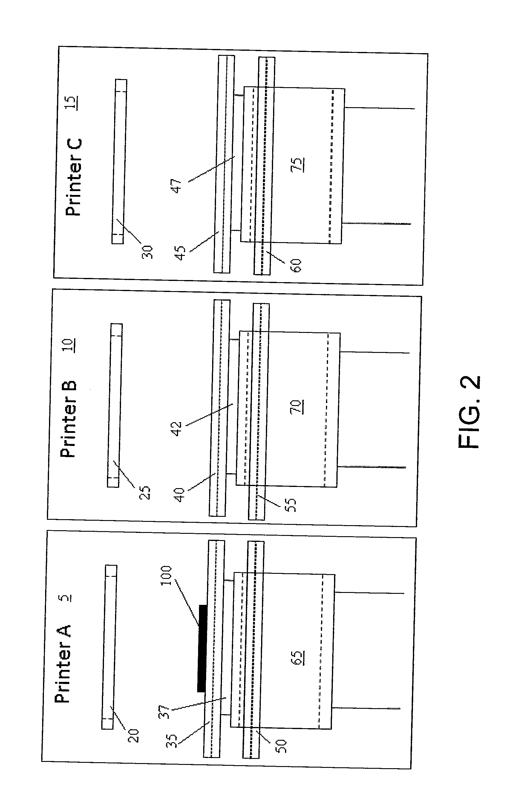
Vertically separated pass through conveyor system and method in surface mount technology process equipment
a conveyor system and vertical separation technology, applied in the field of surface mount technology, can solve the problems of limiting the pass through capacity of the system, unable to easily adjust the lane size, and inability to dynamically sizing the conveyor track to handle different sizes of circuit boards
- Summary
- Abstract
- Description
- Claims
- Application Information
AI Technical Summary
Benefits of technology
Problems solved by technology
Method used
Image

Examples
Embodiment Construction
[0090]It should be understood that the disclosure is not limited in its application to the details of construction and arrangements of the components set forth herein. The disclosure is capable of other embodiments and of being practiced or carried out in various ways. Variations and modifications of the foregoing are within the scope of the present disclosure. It should also be understood that the material disclosed and defined herein extends to all alternative combinations of two or more of the individual features mentioned or evident from the text and / or the drawings. All of these different combinations constitute various alternative aspects of the present disclosure. The embodiments described herein explain the best modes known for practicing the disclosure and will enable others skilled in the art to utilize the disclosure.
[0091]The phraseology and terminology used herein is for the purpose of description and should not be regarded as limiting. The use of “including,”“comprisin...
PUM
| Property | Measurement | Unit |
|---|---|---|
| size | aaaaa | aaaaa |
| vertical travel length | aaaaa | aaaaa |
| viscous | aaaaa | aaaaa |
Abstract
Description
Claims
Application Information