Diesel engine

Active Publication Date: 2010-05-20
MAZDA MOTOR CORP
View PDF10 Cites 19 Cited by
  • Summary
  • Abstract
  • Description
  • Claims
  • Application Information

AI Technical Summary

Benefits of technology

[0007]Accordingly, an object of the present invention is to provide a diesel engine comprising a piston with a cavity at its

Problems solved by technology

If the mixing of the fuel spray from the fuel injector and the air in the cavity was so insufficient that the air-fuel ratio of the mixture did not become properly uniform (homogen

Method used


Image

  • Diesel engine
  • Diesel engine
  • Diesel engine

Examples


embodiment 1

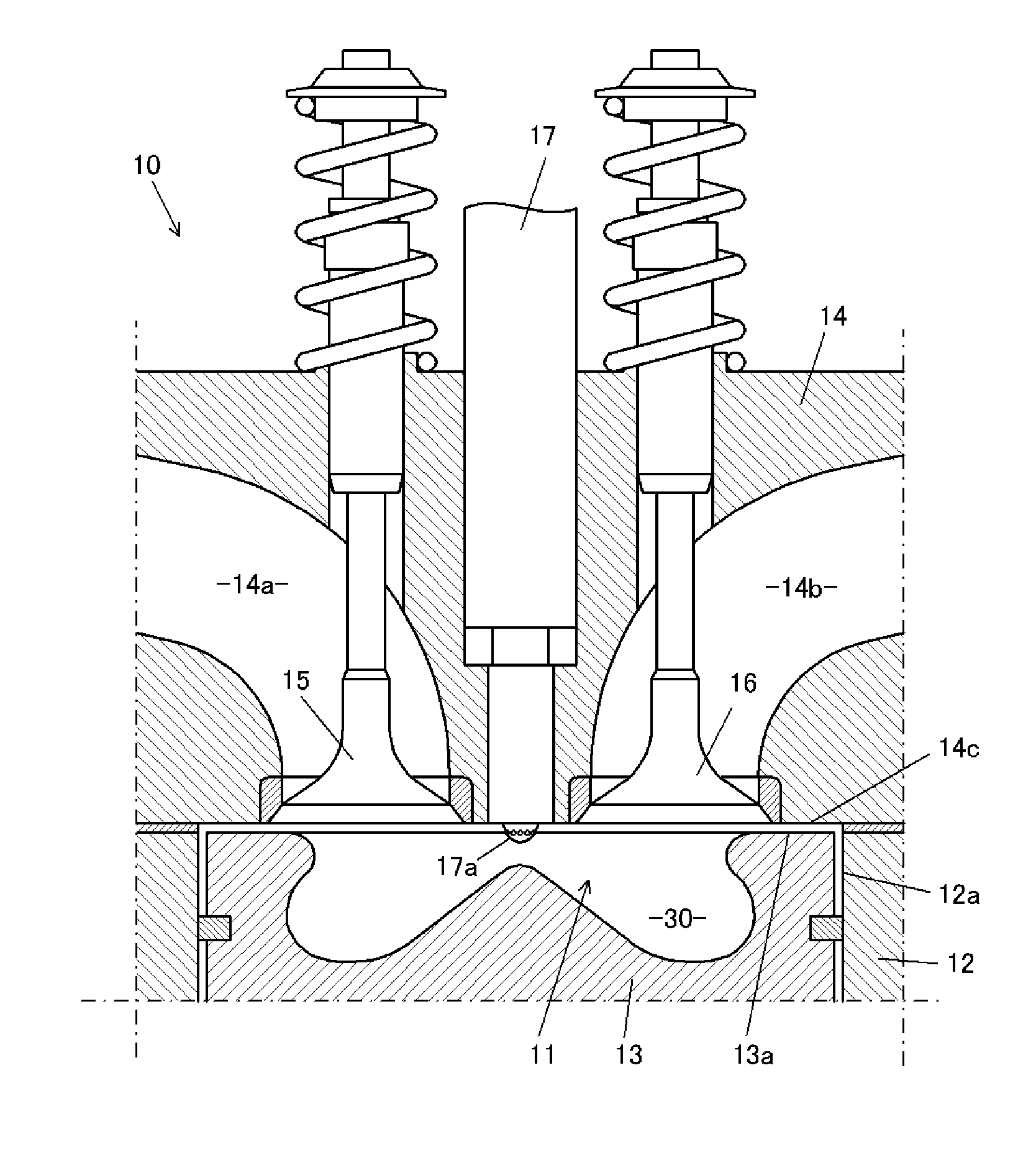
[0034]FIG. 1 shows a structure of a combustion chamber of a diesel engine according to the present embodiment. A combustion chamber 11 of an engine 10 comprises a cylinder 12a which is formed at a cylinder block 12, a top 13a of a piston 13 which reciprocates in the cylinder 12a, and a lower face 14c of a cylinder head 14 at which an intake valve 15 to open or close an intake port 14a and an exhaust valve 16 to open or close an exhaust port 14b are arranged. The lower face 14c faces the piston top 13a.

[0035]Further, a circular cavity 30 is formed on the top 13a of the piston 13 in such a manner that it is concaved away from the lower face 14c of the cylinder head 14. A space of this cavity 30 defines the above-described combustion chamber 1 as well. A fuel injector 17 is attached to the cylinder head 14 so that its tip is positioned at the center of the cavity 30 or the combustion chamber 11.

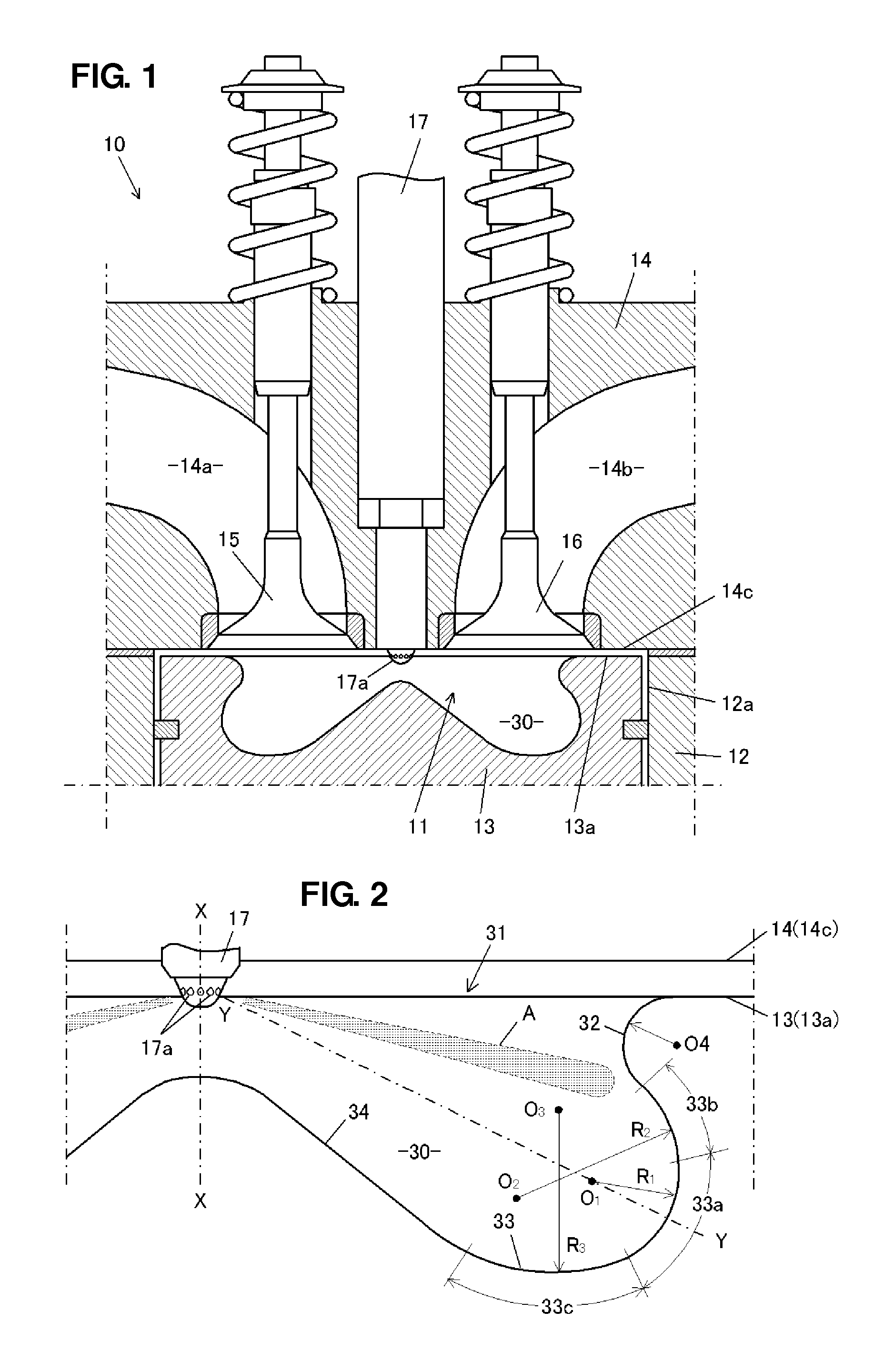
[0036]Next, a wall shape of the cavity 30 on a cross section including a center axis X-X of...

embodiment 2

[0055]Next, a second embodiment of the present invention will be described.

[0056]The present embodiment uses the so-called Cartesian oval curve as the wall shape of the cavity peripheral portion. This oval curve M is shown as gathering of points defined by L1+mL2=a (L1, L2 are respectively distances L1, L2 from its focal points S1, S2; m and a are a constant, respectively) as shown in FIG. 7. Its radius is the shortest at an intersection p of a center line y-y which connects the focal points S1, S2 and the curve M, and its radius gradually increases toward the both sides from the intersection p.

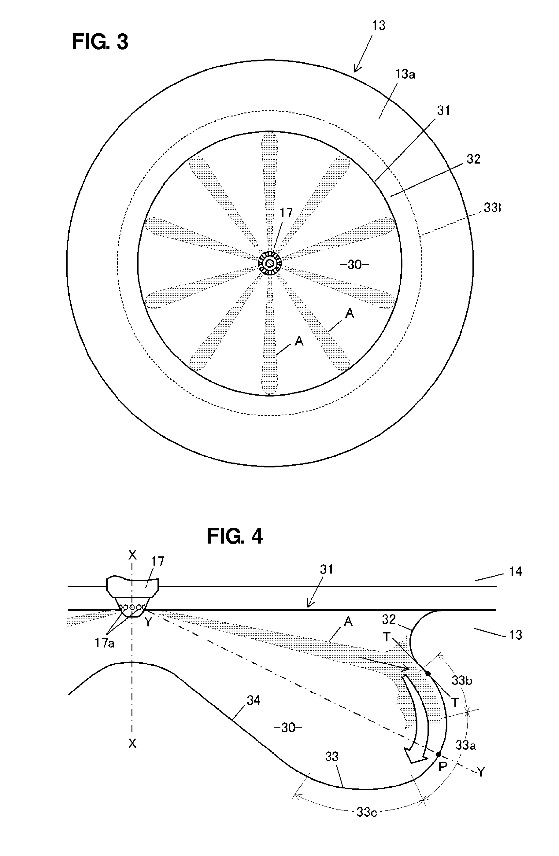
[0057]Herein, as shown in FIG. 8, the above-described center line y-y of the oval curve is matched to the line Y-Y connecting a point P of a peripheral portion 133 of a cavity 130 which is located farthermost from an injection hole 177a of a fuel injector 177 and the injection hole 177a, and the intersection p of the oval curve M and the center line y-y is positioned at the above-described po...


PUM


Abstract

A wall shape of a cavity consists of an inward protruding portion located at the periphery of an opening, a center portion projecting toward a fuel injector, and a peripheral portion connecting the inward protruding portion and the center portion. The fuel injector and the cavity are configured so that fuel injected from fuel injector directs to the proximity of the border between the inward protruding portion and the peripheral portion. The peripheral portion consists of a first portion located farthermost from the fuel injector, a second portion located between the inward protruding portion and the first portion, and a third portion located between the first portion and the center portion. The radii of arcs of the peripheral portion decrease from the second portion to the first portion and increase from the first portion to the third portion.

Description

BACKGROUND OF THE INVENTION[0001]The present invention relates to a diesel engine, and in particular, relates to a combustion chamber structure of the diesel engine which can restrain the soot emission.[0002]In the direct-injection type of diesel engine, in which fuel is injected from the fuel injector which is arranged approximately at the center of the combustion chamber at around the top dead center of compression of the piston, the cavity is formed on the top of the piston and the combustion chamber is defined by the top of the piston including the cavity, the cylinder, and the face of the cylinder head which faces the top of the piston, which is disclosed in Japanese Patent Laid-Open Publication No. 2003-254066, for example.[0003]The above-described cavity is formed in a circular shape with its center at the fuel injector and is concaved away from the cylinder head. Its wall shape on the cross section including the center axis of the cylinder consists of, as shown in FIG. 12, f...

Claims


Application Information

Patent Timeline
IPC IPC(8): F02B3/00F02B23/00
CPCF02B23/0651Y02T10/125F02B23/0672F02B23/0669Y02T10/12
Inventor KIM, SANGKYUSHIMO, DAISUKEKATAOKA, MOTOSHI
Owner MAZDA MOTOR CORP
Why Eureka
Try Eureka