Multi-orifice extrusion die and method for obtaining uniform flow

a technology of extrusion die and multi-orifice, applied in the field of extrusion die, can solve the problems of affecting the flow and velocity of each orifice, affecting the flow of each orifice, and accumulating before, so as to increase or decrease the flow and velocity through each channel individually.

Inactive Publication Date: 2010-05-20
FRITO LAY NORTH AMERICA INC
View PDF27 Cites 5 Cited by
  • Summary
  • Abstract
  • Description
  • Claims
  • Application Information

AI Technical Summary

Benefits of technology

[0009]The current invention discloses a method and apparatus which can be used to produce a plurality of extrudate strands from an extruder which have uniform velocity. The invention uses an extruder system having multiple channels in the die and discloses installing adjustable metering assembly on each channel of the extruder die. Product is then fed through the extruder die and its velocity is measured. The metering assembly at each channel can be adjusted to increase or decrease the flow and velocity through each channel individually. Adjustments are made only when the die is not in operation so that it can be used for hot extrudate subject to curing and gelling. Product is once again introduced into the extruder system and is subsequently measured. Adjustments can then again be made to the metering assemblies. After subsequent iterations each channel can be metered so that each die will exhibit a more uniform velocity. Thus, extrudate strands of uniform velocity can be extruded for a given product at defined operating conditions. Finally, because strands of uniform velocity can be produced, the current invention can be utilized in multi-extrusion processes where it is more desirable that each product have a uniform velocity.

Problems solved by technology

The lack of equal flow from each orifice becomes a difficult problem when, for example, multiple extrudate strands enter crimped cutter rollers.
If the flow from each orifice differs then some strands will be pulled taut, possibly breaking the strand, whereas other strands will be slack, causing them to accumulate before being crimped to the extent that they may interfere with adjacent strands or fold over upon themselves.
This problem is exaggerated when the size of each strand needs to be more uniform for a given product.
However, this method has the disadvantage that it achieves balanced flow only for a narrow range of operating conditions.
Because the die face is not adjustable, fine tuning during production is impossible.
While the referenced prior art may succeed in slightly altering the parabolic flow, the prior art cannot be line tuned to result in approximately uniform velocities.
Additionally, because orifices are placed all around the die face, not just along the periphery, co-extruding in the center of the die face will be difficult.
Because such dies comprise large manifolds, the dough typically has high residence times within the die which may be undesirable for some dough formulations.
Product being exposed to longer residence limes and greater temperatures may cause product degradation in some product dough formulations.
Furthermore, the choker bar method typically requires special expertise to design seals which prevent the extrudate from leaking between the moveable parts of the adjusting mechanism which can significantly increase the cost of the die.
However, the use of CFD requires significant and costly expertise to set up the computational grid to model die designs, and further expense for computing resources.
A further expense is the risk of error in computed results in case error exists in the assumed flow behavior properties of the food material.
The ultimate cost of die design may therefore be judged prohibitive considering the risks.

Method used


Image

  • Multi-orifice extrusion die and method for obtaining uniform flow
  • Multi-orifice extrusion die and method for obtaining uniform flow
  • Multi-orifice extrusion die and method for obtaining uniform flow

Examples


Embodiment Construction

[0017]Several embodiments of Applicants' invention will now be described with reference to the drawings. Unless otherwise noted, like elements will be identified by identical numbers throughout all figures.

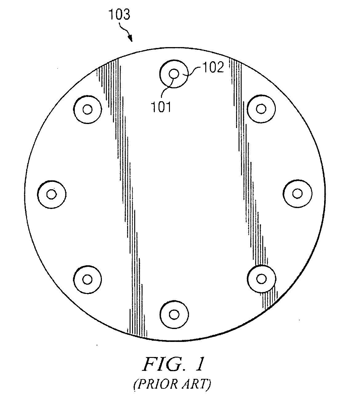
[0018]FIG. 1 shows a planar view of a prior art co-extrusion die face, that can be used with one embodiment of the current invention wherein the co-extrusion die orifices are radially placed around the die face 103. Looking at FIG. 1 it can be seen that each co-extrusion orifice consists of two concentric appertures, an inner round orifice 101 and outer annular orifice 102. The inner orifice 101 represents the orifice where the inner product is introduced to the co-filled product, typically from a separate source. The outer concentric orifice 102 is the orifice where the outer extruded product exits the die face 103. Note that while FIG. 1 is a depiction of a co-extrusion die, the instant invention is not so limited. The instant invention provides a novel apparatus and method of p...


PUM

PropertyMeasurementUnit
residence timeaaaaaaaaaa
mean residence timeaaaaaaaaaa
temperatureaaaaaaaaaa

Abstract

A method for normalizing the exit velocity of multiple extrudate strands from a multiple die extruder and apparatus for producing the same. The invention describes utilizing a die with individual channels, and installing metering assembly on each individual channel. The metering assembly can then be adjusted to independently increase or decrease the velocity of product through an orifice. By independently adjusting individual velocities of extrudate strands, after successive iterations of adjusting, measuring, and readjusting, a plurality of extrudate stands can be produced having substantially uniform velocity. Further the invention can comprise a single extruder or a co-extruder used to make a co-extruded product wherein uniform velocity becomes more desirable.

Description

BACKGROUND OF THE INVENTION[0001]1. Technical Field[0002]The present invention relates to an extrusion die for extruding material through a plurality of die orifices. It especially relates to an extrusion die which produces a plurality of extrudate strands of substantially uniform velocity.[0003]2. Description of Related Art[0004]Extrusion of products of various profile shapes is usually accomplished by extruding through, for example, wide orifices to produce a sheet of extrudate or as another example, through an annular orifice to produce a tubular extrudate. As used herein a channel is a pipe-like feature or conduit through which product can flow, which is located within an extruder die, and which is in fluid communication with an associated orifice. Extrusion dies having multiple extrusion orifices and radial placement are widely used to make direct expanded products to achieve industrial production rates. While radial placement provides a geometrically identical flow path throug...

Claims


Application Information

Patent Timeline
Patent Type & Authority Applications(United States)
IPC IPC(8): B29C47/92B29C48/92B29C48/05B29C48/405
CPCB29C47/0014B29C2947/92828B29C47/0026B29C47/0066B29C47/025B29C47/0828B29C47/124B29C47/128B29C47/30B29C47/40B29C47/92B29C2947/92085B29C2947/92438B29C2947/926B29C47/0021B29C48/92B29C48/05B29C48/08B29C48/10B29C48/0022B29C48/154B29C48/2566B29C48/302B29C48/304B29C48/345B29C2948/92085B29C2948/92438B29C2948/926B29C2948/92828B29C48/405
Inventor KELLER, LEWIS CONRADTATSCH, DONALD JOE
Owner FRITO LAY NORTH AMERICA INC
Why Eureka
Try Eureka